Numerical controller

a controller and number technology, applied in the field of numerical controllers, can solve the problems of tool breakage, increased cutting resistance, abraded cutting edge, etc., and achieve the effect of improving tool life determination and reducing tool cos

Active Publication Date: 2019-05-21
FANUC LTD
View PDF4 Cites 4 Cited by
  • Summary
  • Abstract
  • Description
  • Claims
  • Application Information

AI Technical Summary

Benefits of technology

[0012]An object of the present invention is to provide a numerical controller which enables highly-accurate tool life determination.
[0013]In the present invention, the above-mentioned problems are solved by providing a numerical controller with a function for learning a relationship between a machining condition and a machining result through supervised learning and improving input data based on the obtained learning result. The numerical controller according to the present invention is capable of continuing a machining operation while keeping a certain level of quality by improving input data based on learning results.
[0016]Thus, the numerical controller according to the present invention has the above-mentioned configuration. Accordingly, reduction in tool cost can be expected due to improvement of tool life determination and an unattended continuous operation can be assisted.

Problems solved by technology

As for a general tool used in machining, a cutting edge is abraded away and cutting resistance is increased with the elapse of machining time, and eventually the tool is broken.
Further, machining accuracy is degraded along with progress of abrasion and accordingly, it becomes impossible to maintain predetermined machining accuracy required for a workpiece.
However, the above-mentioned method for determining a tool life has various problems.
In the method for determining a tool life based on the number of times or time in which the tool is used, a lifetime value is commonly set by more than enough number of times of use or use time so as to avoid machining defects or breakage, so that the tool is often still usable and thus the cost is wasted.
The method for determining a tool life based on the tool length of a tool has such a problem that it is impossible to detect cracks of a chip in the case where there are a plurality of blades or where a blade is positioned at the end.
Further, in the case of a tool whose life is determined based on abrasion on a portion other than the end portion, such as a tapping tool, it is impossible to determine a tool life by measurement of the end portion.
In the method for determining a tool life based on operator's visual check of a machined workpiece, an operator having technical knowledge needs to perform the operation and thus, this method is not suitable for an unattended operation.
In the method for determining a tool life by checking a spindle load, slight chipping hardly causes change of the spindle load, causing difficulty in accurate detection.
However, the tool life cannot be determined merely based on the abrasion amount of a tool.
Thus, the technique of Japanese Patent Application Laid-Open No. 2000-198047 still has a problem that the technique cannot cope with various situations.

Method used


Image

  • Numerical controller
  • Numerical controller
  • Numerical controller

Examples


Embodiment Construction

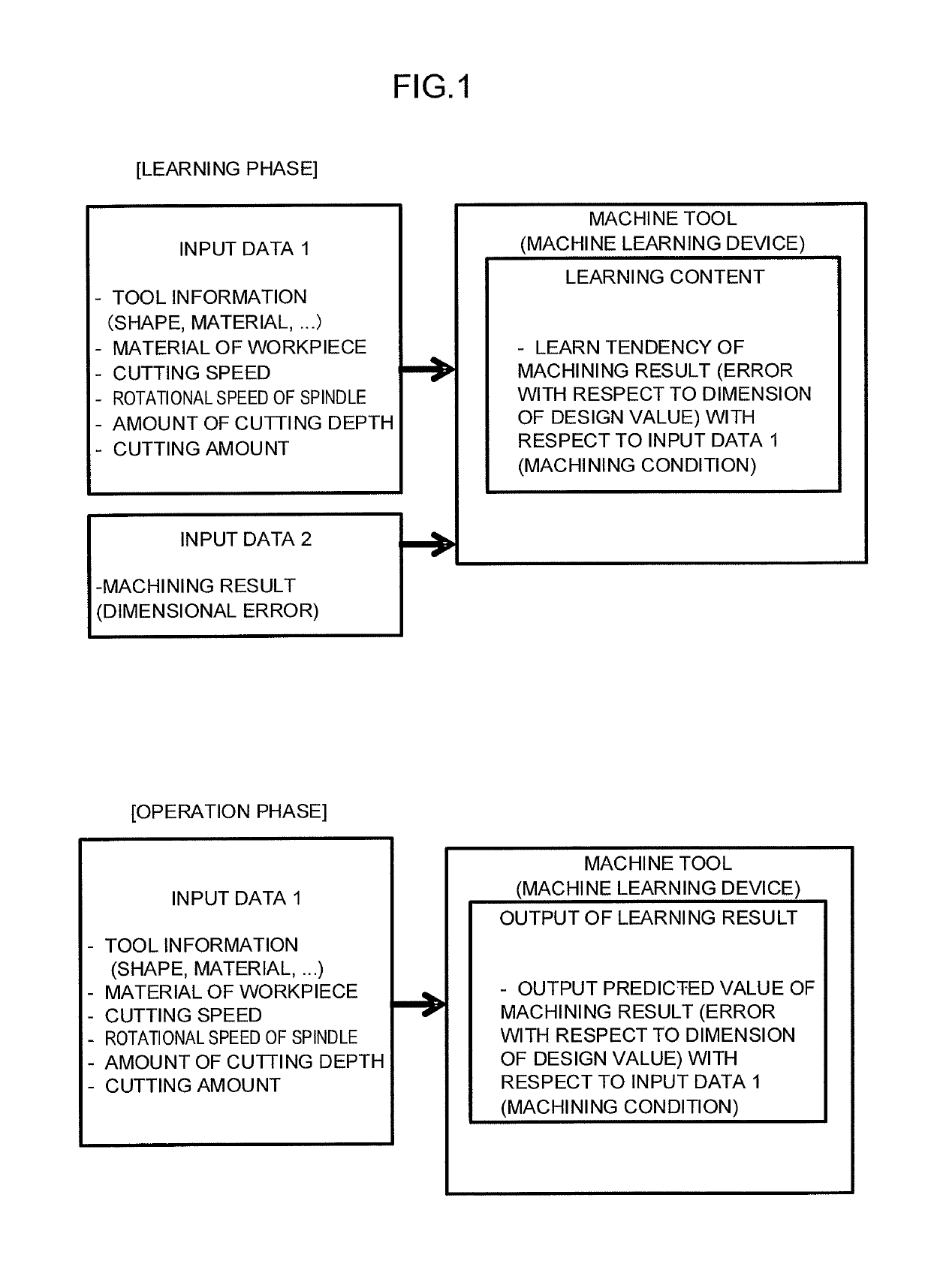
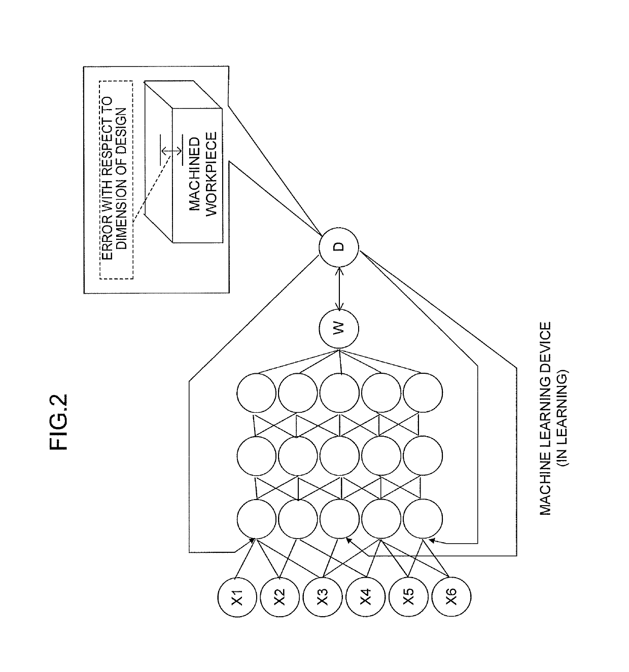
[0026]FIG. 1 illustrates an outline of machine learning and application of a learning result by a machine learning device which is introduced to a numerical controller in the present invention. The machine learning device introduced to the numerical controller according to the present invention operates in two phases which are a learning phase and an operation phase.

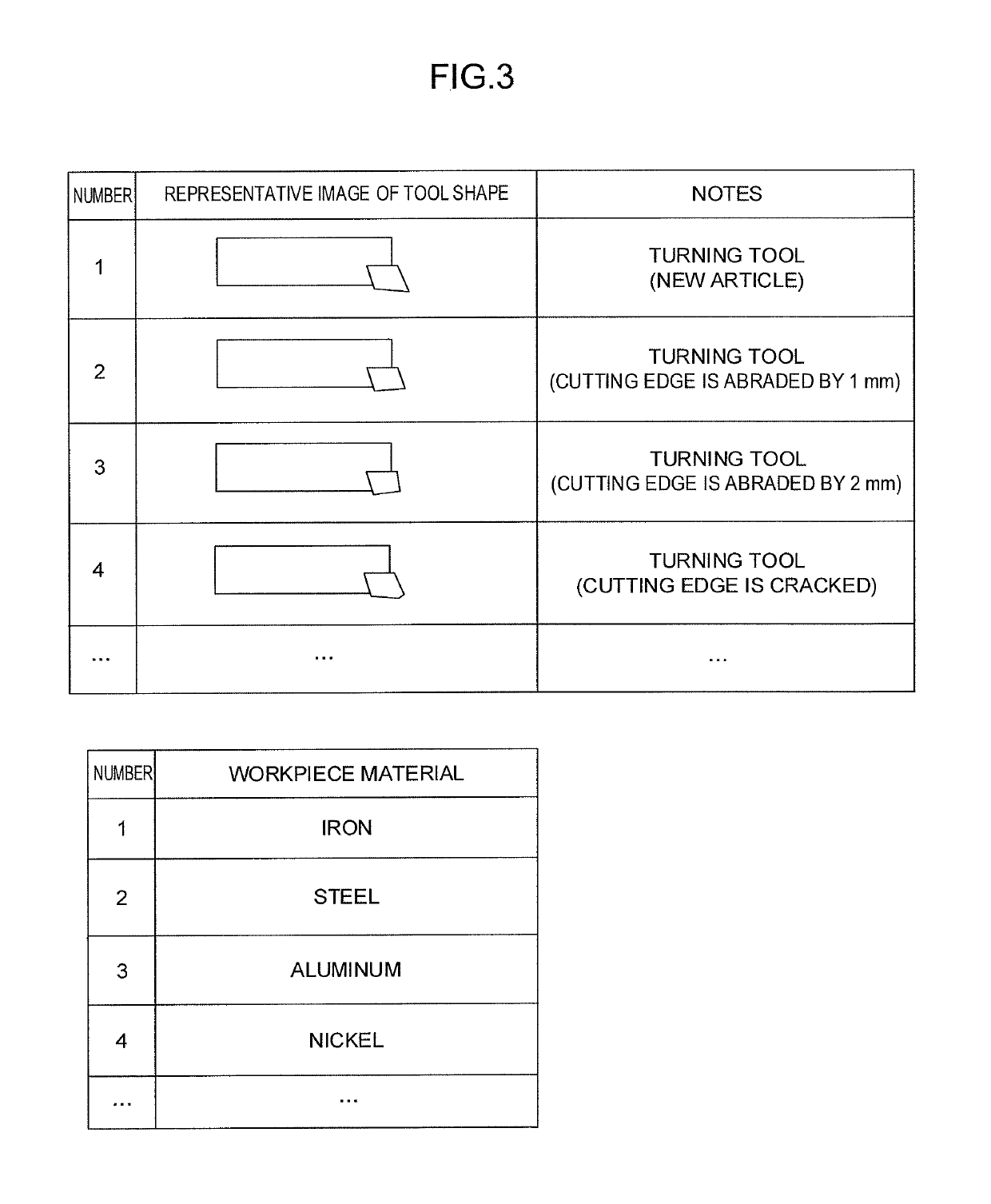
[0027]In the learning phase, the machine learning device introduced to the numerical controller according to the present invention uses, as input data, machining conditions such as tool information, a material of a workpiece, a cutting speed, a rotational speed of a spindle, an amount of cutting depth, and a cutting amount and a machining result such as a dimensional error of a workpiece machined based on the machining conditions so as to learn tendency of the machining result with respect to the machining conditions.

[0028]In the operation phase, the numerical controller according to the present invention provides machin...


PUM


Abstract

A numerical controller which controls a machine tool acquires tool information including a shape of a tool, a machining condition in machining, and information related to a machining result of a workpiece after machining. A machine learning device performs machine learning on tendency of the information related to a machining result with respect to the tool information and the machining condition based on the tool information and the machining condition used as input data and based on the information related to a machining result used as teacher data, so as to construct a learning model. The machine learning device determines whether or not a machining result is good by using the learning model based on the tool information and the machining condition before the machine tool machines a workpiece.

Description

BACKGROUND OF THE INVENTION[0001]1. Field of the Invention[0002]The present invention relates to a numerical controller, and especially relates to a numerical controller which learns a tool state causing machining defects.[0003]2. Description of the Related Art[0004]As for a general tool used in machining, a cutting edge is abraded away and cutting resistance is increased with the elapse of machining time, and eventually the tool is broken. Further, machining accuracy is degraded along with progress of abrasion and accordingly, it becomes impossible to maintain predetermined machining accuracy required for a workpiece. In order to avoid such matter of tools, whether or not a tool has reached the end of life is determined mainly at the following timing, and tool exchange is performed when it is determined that the tool has reached the end of life.[0005]At a time at which the number of times or time in which the tool is used exceeds a certain number (life value)[0006]At a time at whic...

Claims


Application Information

Patent Timeline
Patent Type & Authority Patents(United States)
IPC IPC(8): G05B19/406G06N99/00G06N20/00G05B19/4093G06N3/08
CPCG05B19/406G05B19/40932G06N20/00G06N3/084G05B2219/49307G05B2219/33321G05B19/19G05B2219/32416G05B19/4065
Inventor SAITOU, TAKUYAMATSUKAWA, TOSHINORI
Owner FANUC LTD
Why Eureka
Try Eureka