Integral tandem bearing for high speed flexible shafts

a technology of high-speed flexible shafts and tandem bearings, which is applied in the direction of bearing unit rigid support, machines/engines, mechanical equipment, etc., can solve the problems of front bearing design affecting the overall engine weight, time of engine assembly, and bearing cos

Active Publication Date: 2008-03-13
PRATT & WHITNEY CANADA CORP
View PDF9 Cites 26 Cited by
  • Summary
  • Abstract
  • Description
  • Claims
  • Application Information

AI Technical Summary

Benefits of technology

[0003]It is therefore an object of this invention to provide improved bearings for gas turbine shafts.

Problems solved by technology

Arrangement and design of the front bearings impact the overall engine weight, time of engine assembly and cost of the bearings.

Method used


Image

  • Integral tandem bearing for high speed flexible shafts
  • Integral tandem bearing for high speed flexible shafts
  • Integral tandem bearing for high speed flexible shafts

Examples


Embodiment Construction

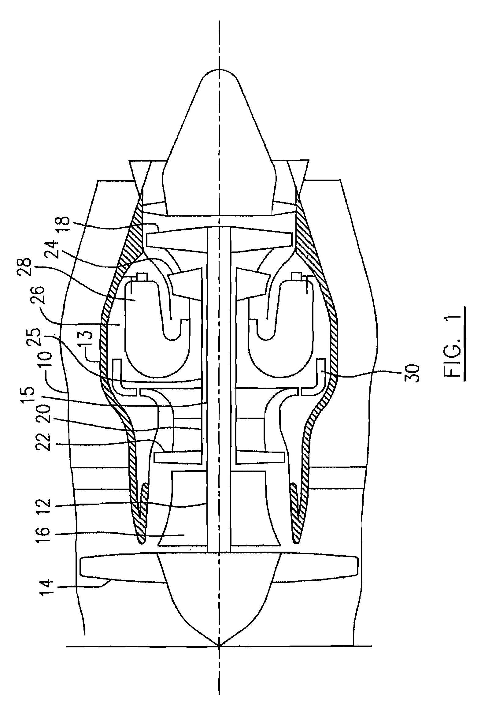
[0013]Referring to FIG. 1, a turbofan gas turbine engine incorporating an embodiment of the present invention is presented as an example of the application of the present invention, and includes an outer casing 10, a core casing 13, a low pressure spool assembly seen generally at 12 which includes a shaft 15 interconnecting a fan assembly 14, a low pressure compressor 16 and a low pressure turbine assembly 18, and a high pressure spool assembly seen generally at 20 which includes a shaft at 25 interconnecting a high pressure compressor assembly 22 and a high pressure turbine assembly 24. The core easing 13 surrounds the low and high pressure spool assemblies 12 and 20 and defines a main gas path (not indicated) therethrough. In the main gas path there are provided a combustion section 26 having a combustor 28 therein. Pressurized air provided by the high pressure compressor assembly 22 through a diffuser 30 enters the combustion section 26 for combustion taking place in the combusto...


PUM


Abstract

An integral tandem bearing assembly for supporting a main shaft in a gas turbine engine is provided. The tandem bearing assembly comprises two bearing assemblies connected by integrated inner ring.

Description

TECHNICAL FIELD[0001]The invention relates generally to gas turbine engines and, more particularly, to gas turbine engines having an improved bearing structure to support high speed flexible shafts.BACKGROUND OF THE ART[0002]Gas turbine engines such as those used as aircraft turbojets or turbofans typically comprise a rotating fan, compressor and turbines that are mounted to one or more coaxial shafts rotating about a central axis of the engine. One a turbofan engine, a fan and low pressure compressor at the front end of the engine are connected by a long flexible shaft to a low pressure turbine at the rear end of the engine to form a low pressure spool assembly. Often the flexible shaft is supported by three bearings (two bearings at the front fan end, and one at the rear turbine end) to achieve acceptable rotor-dynamic behaviour within the engine. Alternatively, the two bearings at the front fan end may be configured as a robust, single front bearing when thicker shafts are utiliz...

Claims


Application Information

Patent Timeline
Patent Type & Authority Applications(United States)
IPC IPC(8): F16C19/49
CPCF01D25/16F01D25/164F16C2360/23F16C19/54F16C35/061F16C19/49
Inventor BRUNO, VITTORIODUSZA, EDWARDLABBE, MICHELURAC, TIBOR
Owner PRATT & WHITNEY CANADA CORP
Why Eureka
Try Eureka