
Controller for a video matrix switching system

a video matrix and control board technology, applied in the field of closed circuit television systems, can solve the problems of high system cost, difficult to increase the number of ports above a predetermined amount, and high cos

Inactive Publication Date: 2008-03-13
SENSORMATIC ELECTRONICS CORP
View PDF16 Cites 4 Cited by
  • Summary
  • Abstract
  • Description
  • Claims
  • Application Information

AI Technical Summary

Benefits of technology

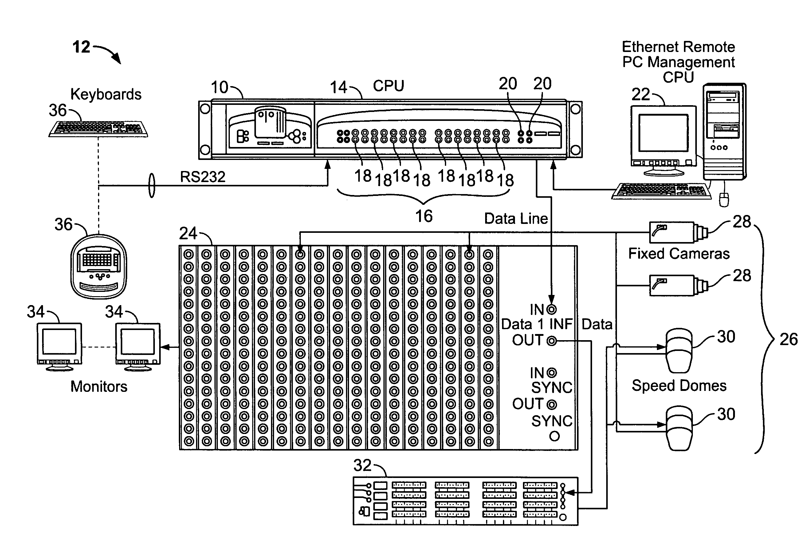
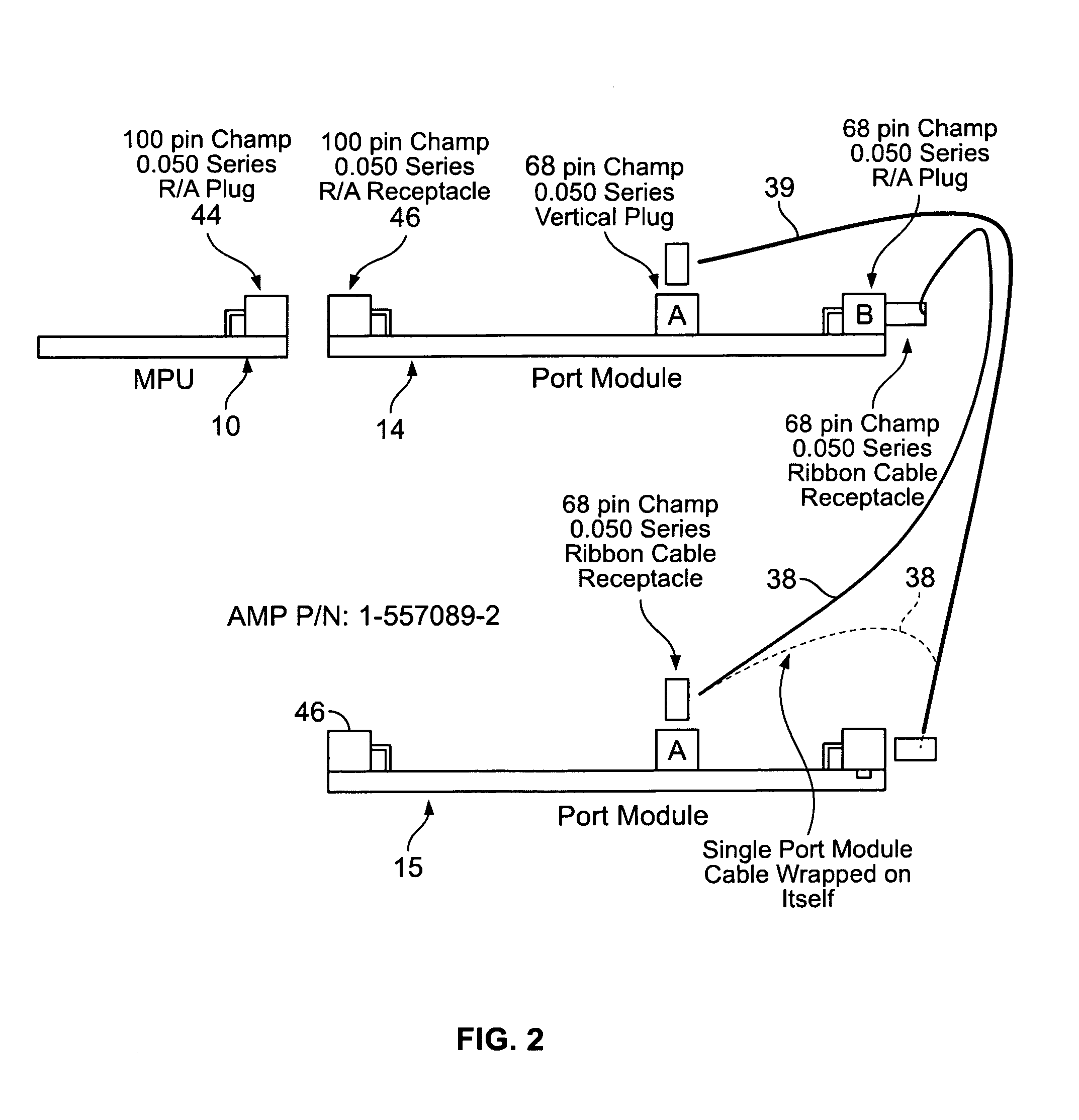
The patent describes a controller for a video matrix switching system that can control a large number of cameras and displays using high-speed data lines and RS-232 ports. The controller includes a multiple purpose unit (MPU) module and a port module with driver electronics for interface ports. The interface ports include both communication ports and data line ports. The MPU module also includes a watchdog module to monitor and take action when specified tasks time out. The controller reduces the number of component parts required and avoids the use of relay technology. The technical effect of the patent is to provide a hot switched, stand-by CPU that can control a large video matrix system efficiently and effectively.

Problems solved by technology

However, large CCTV systems with hot switch products require extra modules and / or physical boxes and significantly increase system cost as the number of ports increases.
Increasing the number of ports above a predetermined amount is difficult and expensive.

Method used


Image

  • Controller for a video matrix switching system
  • Controller for a video matrix switching system
  • Controller for a video matrix switching system

Examples


Embodiment Construction

[0017]As used herein, an element or step recited in the singular and proceeded with the word “a ” or “an ” should be understood as not excluding plural of said elements or steps, unless such exclusion is explicitly stated. Furthermore, references to “one embodiment” of the present invention are not intended to be interpreted as excluding the existence of additional embodiments that also incorporate the recited features. Moreover, unless explicitly stated to the contrary, embodiments “comprising ” or “having ” an element or a plurality of elements having a particular property may include additional such elements not having that property.

[0018]Certain terms used herein may be defined as follows:

[0019]Selected Unit: This term refers to a multiple purpose unit (MPU) module that may actively drive data line ports and communications port transmitters. Because both MPU modules of a connected pair may be powered and actively processing incoming data, the term “selected ” as used herein iden...


PUM


Abstract

A controller for a video matrix switching system may include at least a first multiple purpose unit (MPU) module configured to provide video and control for a multi-camera video CCTV system, and at least a first port module connectable to the MPU module and having driver electronics for a set of interface ports. In some, but not necessarily all embodiments, the interface ports may include both a plurality of communications ports and one or more data line ports. Also, the MPU module may include a watchdog module configured to present an interface that monitors specified tasks and takes action when any of the specified tasks time out.

Description

BACKGROUND OF THE INVENTION[0001]1. Field of the Invention[0002]This invention relates generally to closed circuit television systems, and more particularly, to modular controllers for video switching systems.[0003]2. Description of the Related Art[0004]The largest and most sophisticated users of closed circuit television (CCTV) systems include airports, corporate or government complexes, casinos, and large medical centers. CCTV systems installed by such users may start with a single central processing unit (CPU) and switcher bay, but many users will eventually need to install upgrades and enhancements as their needs grow. Such enhancements may include expansion of the number of CCTV cameras from tens or hundreds up to a thousand or more.[0005]At least one known expanded CCTV system has utilized two independent central processing units (CPUs) and a hot switch product that senses the operation of the CPUs. The hot switch product has double pole relays configured to switch controlling...

Claims


Application Information

Patent Timeline
Patent Type & Authority Applications(United States)
IPC IPC(8): H04N7/18
CPCH04N5/268H04N7/18H04Q2213/13332H04Q2213/13106H04Q2213/13003
Inventor SCHIELTZ, STENVEN W.PAOLANTONIO, JAMES R.MCBRIDE, MONTE CHARLESBARCALA, SERGIOANDERSON, LUIS
Owner SENSORMATIC ELECTRONICS CORP
Learn More