Linear lamp replacement

a technology for replacing lines and lamps, applied in semiconductor devices, light source combinations, lighting and heating apparatus, etc., can solve the problems of limited efficacy, inoptimized 360 degree light distribution, limited life of fluorescent tubes, etc., to reduce or minimize the number of light bounces, the effect of reducing glar

Active Publication Date: 2017-10-19
SATCO PRODS
View PDF3 Cites 2 Cited by
  • Summary
  • Abstract
  • Description
  • Claims
  • Application Information

AI Technical Summary

Benefits of technology

[0004]Aspects of the invention are directed to a light source made up of light emitting elements attached to a PCB or flex circuit and in contact with a support structure and heat dissipating element, and directed toward at least one partially reflecting reflector and away from the primary direction of the intended illumination. Orienting the LEDs directly opposite the work surface can reduce glare and can reduce or minimize the number of light bounces before exiting the lamp in the direction of the work surface.
[0005]The light emitting elements may include one, two or more colors or color temperatures. The support structure can also be an optical element. The heat dissipating element may also be an optical element. The cross-sectional width of the light source may be elliptical-like. The cross-sectional width of the light source can have two distinct widths the larger of the two improves optical efficiency and the smaller of the two provides mechanical and electrical compatibility with T8 size fluorescent lamps or other lamp sizes between T50 and T5.

Problems solved by technology

Fluorescent tubes have lifetimes limited by on / off cycles, a 360 degree light distribution that is not optimal (half goes into the room, half goes toward the ceiling), limited efficacy, and contains mercury.
However, a common problem with LED solutions is a non-optimal compromise between efficiency and glare.
To control glare the common approach is to use a diffuser which can be inefficient.
Efficient solutions often orient the LED in direct line of sight to the work surface causing eye discomfort from bright spots of light.

Method used


Image

  • Linear lamp replacement
  • Linear lamp replacement
  • Linear lamp replacement

Examples


Embodiment Construction

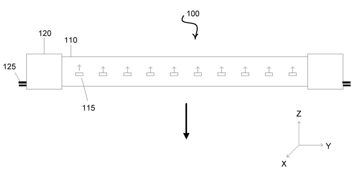
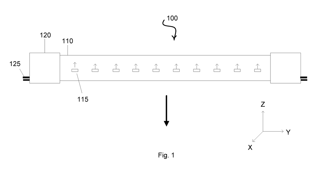
[0013]The invention provides systems and methods for providing illumination. A linear replacement light may be provided to replace fluorescent tubes. Various aspects of the invention described herein may be applied to any of the particular applications set forth below or for any other types of lighting configurations. The invention may be applied as a standalone device or method, or as part of an integrated lighting system. It shall be understood that different aspects of the invention can be appreciated individually, collectively, or in combination with each other.

[0014]An efficient light source can be desirable for mass adoption in an industrial society. Beyond energy efficiency there are numerous other characteristics that can be desirable in a light source. Descriptions provided elsewhere herein provide examples of desirable characteristics, which are not limiting or exhaustive.

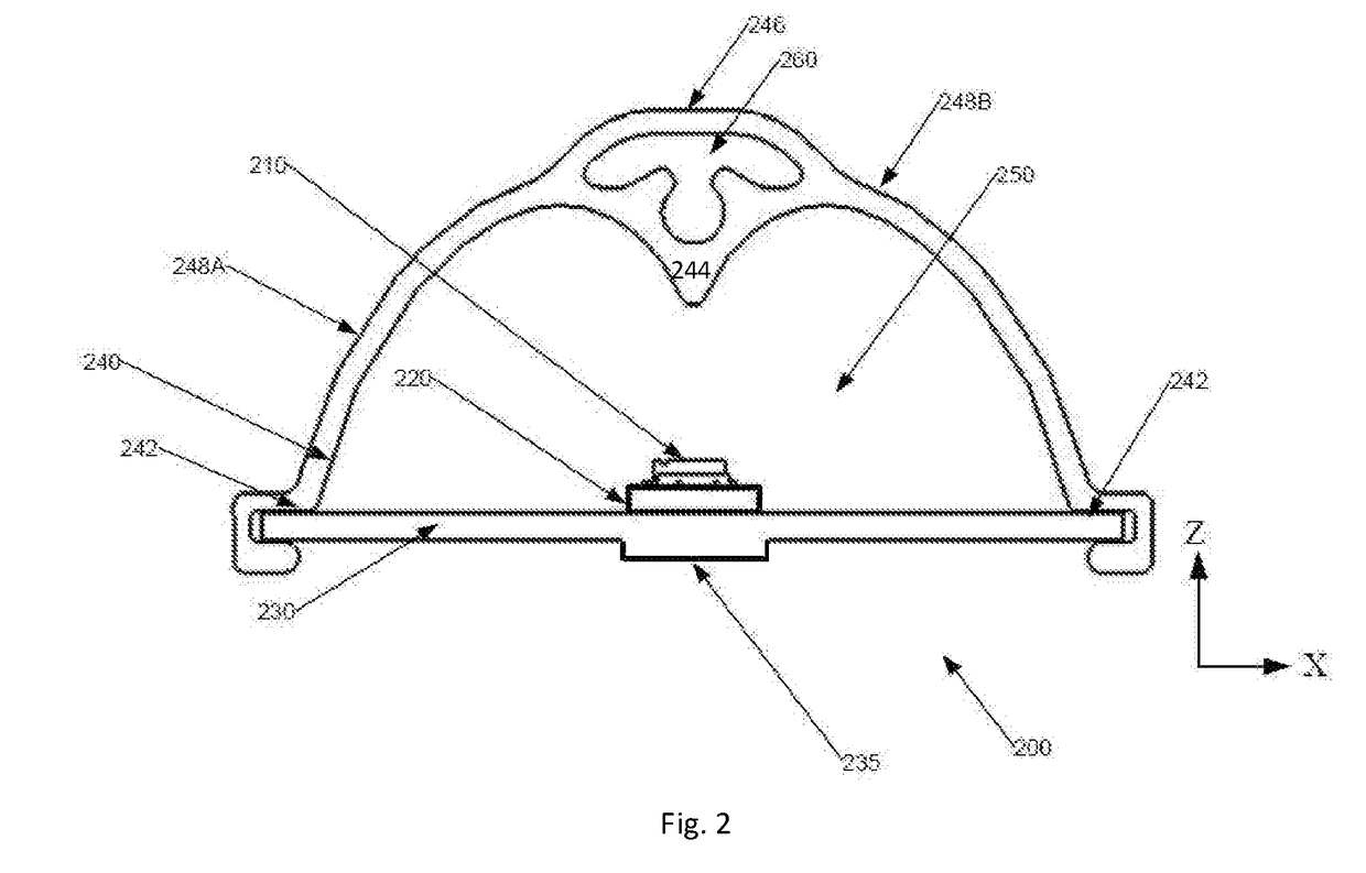
[0015]It can be generally desirable to have control over the distribution of optical radiation out of ...


PUM


Abstract

A linear lamp is provided having one or more light emitting elements provided therein. The light emitting elements are directed to emit light in a direction different from the primary direction of the illumination of the lamp. The light emitting elements may be supported by a supporting optical element. The supporting optical element may permit the transmission of light therethrough. The supporting optical element may be an integral window upon which the light emitting elements are disposed.

Description

CROSS-REFERENCE[0001]This Application is a continuation application of U.S. patent application Ser. No. 14 / 526,328, filed on Oct. 28, 2014, which application claims the benefit of U.S. Provisional Application No. 61 / 896,491 filed Oct. 28, 2013 and U.S. Provisional Application No. 61 / 903,339 filed Nov. 12, 2013, all of which applications are incorporated herein by reference in their entirety.BACKGROUND OF THE INVENTION[0002]Currently, many lighting systems use fluorescent tubes to provide illumination. Fluorescent tubes have lifetimes limited by on / off cycles, a 360 degree light distribution that is not optimal (half goes into the room, half goes toward the ceiling), limited efficacy, and contains mercury. Light emitting diode (LED) solutions can solve many of the challenges faced by fluorescent tubes. However, a common problem with LED solutions is a non-optimal compromise between efficiency and glare. To control glare the common approach is to use a diffuser which can be inefficien...

Claims


Application Information

Patent Timeline
Patent Type & Authority Applications(United States)
IPC IPC(8): F21K9/60F21V19/00F21V13/02F21K9/27F21V29/503F21V3/00F21V23/00F21K9/64F21V5/00
CPCF21V29/503F21K9/60F21V13/02F21V23/005F21V3/00F21V5/00F21V19/0045F21K9/27F21K9/64F21Y2103/10F21Y2115/10F21Y2113/13F21K9/66F21V5/10F21V13/08
Inventor KATONA, THOMASPAOLINI, STEVENLEONARD, ROBERT
Owner SATCO PRODS
Why Eureka
Try Eureka