Air controlled electrospray manufacturing and products thereof

a technology of electrospray droplets and air control, which is applied in the direction of coatings, transportation and packaging, and material granulation, etc., can solve the problems of high throughput production rate and inefficient formation of uniform and/or thin coatings and films, and achieve enhanced deformation of electrospray droplets, high production rate, and high speed

Active Publication Date: 2018-12-27
CORNELL UNIVERSITY
View PDF0 Cites 0 Cited by
  • Summary
  • Abstract
  • Description
  • Claims
  • Application Information

AI Technical Summary

Benefits of technology

[0005]In certain embodiments, provided herein is a process for manufacturing an material (e.g., film or coating), the process comprising generating a plume or aerosol from a fluid stock. Generally, the fluid stock comprises a liquid and an optional inclusion, such as a micro- and / or nano-structured solid particles, a metal precursor, a ceramic precursor, a polymer, or the like, or a combination thereof. In specific embodiments, the plume or aerosol is generated using a suitable technique, such as an electrospray technique. In some embodiments, the process further comprises generating the plume or aerosol in the presence of a high velocity gas. In specific instances, the high velocity gas facilitates the fine dispersion of the plume or aerosol particulates, which, in turn, facilitates the controlled and uniform deposition of the liquid and / or inclusion parts on a substrate surface. In some instances, the direction of the flow of the gas and the plume / aerosol are in the same general direction (e.g., having a directional mean within 15 degrees, 10 degrees, 5 degrees, or the like of each other).
[0008]In some instances, ejecting of a fluid stock (e.g., charged fluid stock) from a nozzle (e.g., electrospray nozzle) produces a fluid jet, which is disrupted to form a plume comprising a plurality of droplets (or plume particulates). In certain instances, such droplets are in varying states of dryness (e.g., wherein more dry droplets comprise less fluid medium relative to solid inclusion materials) as they move toward a collector, with the droplets near the collector being dryer (i.e., comprising less fluid medium) (or even completely dry) than those droplets near the nozzle. In some instances, the plume comprises (e.g., especially in closest proximity to the collector substrate) droplets wherein all fluid medium has been evaporated. In preferred embodiments, plume droplets (particularly in proximity to the collector substrate surface) are disrupted and small enough to reduce or minimize the number and / or amount of inclusions included within each droplet. In certain instances, reducing and / or minimizing the number and / or amount of inclusions in each droplets facilitates good distribution of inclusion throughout the plume, particularly in proximity to the collector. In some instances, good distribution of inclusions within the plume facilitates good distribution of inclusions as collected on the collector substrate. In particular, films and coatings suffer from poor performance characteristics due to lack of uniformity of the film or coating (e.g., due to variations in dispersion and / or concentration of inclusions / additives, variations in film / coating thickness, etc.).
[0010]In certain instances, processes herein comprise generating a plume or aerosol (e.g., electrospraying a fluid stock) with a high velocity gas (e.g., ≥0.1 m / s, ≥0.5 m / s, ≥1 m / s, ≥5 m / s, ≥10 m / s, ≥20 m / s, ≥25 m / s, ≥50 m / s). In some instances, an electrostatically charged fluid stock is injected into a stream of high velocity gas. In certain instances, the high velocity gas facilitates further disruption (e.g., breaking apart) of the droplets formed during electrospray of the fluid stock. In some embodiments, droplets of the plume comprise (e.g., on average) less than 100 inclusions (e.g., sum of inclusion(s) in the droplets), less than 50 inclusions, less than 20 inclusions, less than 10 inclusions or the like. In specific embodiments, the collector is a distance d away from the nozzle and the droplets of the plume within d / 2, d / 3, or d / 4 away from the collector comprise (e.g., on average) about 100 inclusions or less, about 50 inclusions or less, about 20 inclusions or less, about 10 inclusions or less, about 5 inclusions or less, about 3 inclusions or less, or the like. In some instances, the good dispersion of the droplets and the low concentration of inclusions per droplets facilitates the formation of a well-dispersed and well-controlled systems (e.g., multi-component systems), such as described herein.
[0012]In certain embodiments, processes and systems described herein are suitable for high throughput of heavily loaded fluid stocks. In particular, in some instances, such as wherein electrospray processes occur with a gas stream, higher loading of particles and / or inclusions are possible. In addition, in some embodiments, high concentrations of inclusion components are preferred in order to facilitate good coverage of a surface (of a collector or substrate), good uniformity of films (e.g., thickness, dispersion, etc.), and / or the like. In certain embodiments, the fluid stock provided herein comprises at least 0.1 wt. %, at least 0.5 wt. %, or at least 1 wt. % inclusion component, e.g., at least 2 wt. % inclusion component, at least 2.5 wt. % inclusion component, at least 3 wt. % inclusion component, at least 5 wt. % inclusion component, or the like (e.g., up to 50 wt. %, up to 30 wt. %, up to 20 wt. %, up to 15 wt. %, up to 10 wt. %, or the like). In certain embodiments, the fluid stock comprises about 2 wt. % to about 15 wt. % (e.g., about 10 wt. % to about 15 wt. %) inclusion component.
[0031]In addition, provided herein are scalable manufacturing processes for the fabrication of new materials (e.g., depositions) with tailored nanostructures, e.g., meeting an unmet need. In some embodiments, processes and systems provided herein (e.g., gas controlled electrospray processes and systems) employ high speed, circumfenerentially uniform air flow that can provide enhanced deformation of electrospray droplets (and / or particles), offering a high production rate (tens to hundreds of folds higher than other electrospray techniques), better control of dispersion of inclusions (e.g., nanoinclusions) in the droplets, and / or better control of directing droplets toward a collector with more uniform and thin depositions (e.g., films and coatings).

Problems solved by technology

Conventional electrospray is effective in creating small charged drops for ionization, atomization and aerosol applications, but inefficient at forming uniform and / or thin coatings and films, particularly at high throughput production rates.

Method used


Image

  • Air controlled electrospray manufacturing and products thereof
  • Air controlled electrospray manufacturing and products thereof
  • Air controlled electrospray manufacturing and products thereof

Examples


example 1

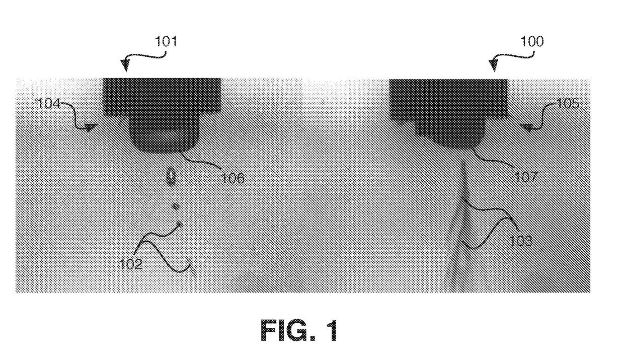
[0097]A fluid stock comprising 3 wt. % polyvinylalcohol (PVA) in water is prepared. The solution is provided to a non-gas-controlled electrospray nozzle, to which a direct voltage of about 10 kV to about 15 kV is maintained. A grounded collector is positioned opposite the electrospray nozzle, at a distance of about 20 cm to about 25 cm. High speed imaging of the electrospray process is illustrated in FIG. 1 (left panel), and a PVA deposition is collected on the collector, as illustrated in FIG. 2 (left panels). As is illustrated in FIG. 2, the deposition is irregular, with large PVA beads being evident.

[0098]A 3 wt. % PVA solution is also electrosprayed by injecting the solution into a gas (air) stream (Qair of about 11 SCFH) using a coaxially configured nozzle as described herein. A direct voltage of about 10 kV to about 15 kV is maintained at the nozzle. A grounded collector is positioned opposite the electrospray nozzle, at a distance of about 20 cm to about 25 cm. High speed ima...

example 2

[0099]A fluid stock comprising polycarbonate, silica nanoparticles, organic polysilazane, and fluoroalkyl silane in a ratio of about 20 / 30 / 49 / 1 is prepared in DMF (additive:liquid medium=5:95). The fluid stock is electrosprayed on a glass substrate using a non-gas controlled process and a gas-controlled process similar to Example 1. FIG. 9 illustrates the surface coated using a gas-controlled process. Surfaces prepared according to both processes are tested for hydrophobicity, the gas-controlled process yielding a surface having a contact angle (of water) of about 136 degrees (as illustrated by FIG. 9), whereas the base glass has a contact angle of about 104 degrees and the non-gas-controlled process yields a surface having a contact angle (of water) of about 120 degrees. A surface is also manufactured using an air-only spray process, such process yielding a surface having a contact angle of about 126 degrees. Further, as illustrated in FIG. 4, the coated glass substrate retains goo...

example 3

[0100]A viscous fluid stock comprising graphene oxide (0.75 wt. %) in an aqueous medium (additive:liquid medium=0.75:99.25). The fluid stock is electrosprayed on a metal (substrate using a non-gas controlled process and a gas-controlled process similar to Example 1. For comparison, a system using graphene oxide (0.75 wt %) in an aqueous medium is electrosprayed with and without a high velocity gas stream. Similar conditions are utilized, with a working voltage of 25 kV, a distance from the nozzle to the collector of 20 cm, and a flow rate of 0.07 mL / min. As illustrated in the SEM images of FIG. 12 (panel A) after 30 seconds of gas controlled electrospraying of the stock, the beginning of the formation of a fine film of graphene oxide is observed. By contrast as illustrated in FIG. 12 (panel B) after only 30 seconds of electrospraying of the stock without air, large droplets and collections of graphene oxide are observed on the substrate. As illustrated in FIG. 13 (panel B), after ju...


PUM

PropertyMeasurementUnit
velocityaaaaaaaaaa
thicknessaaaaaaaaaa
thicknessaaaaaaaaaa

Abstract

Provided in certain embodiments herein are gas controlled electrospray systems and processes for manufacturing depositions, such as thin layer films. In some embodiments, processes and systems provided herein are suitable for and configured to manufacture uniform depositions, such as having uniform thickness.

Description

CROSS-REFERENCE[0001]This application claims the benefit of U.S. Provisional Application Nos. 62 / 254,392, filed Nov. 12, 2015, 62 / 254,405, filed Nov. 12, 2015, and 62 / 354,366, filed Jun. 24, 2016, all of which are incorporated herein by reference in their entireties.FIELD OF THE INVENTION[0002]The field relates films, coatings and depositions, particularly as prepared by electrospray techniques.BACKGROUND OF THE INVENTION[0003]Conventional electrospray is effective in creating small charged drops for ionization, atomization and aerosol applications, but inefficient at forming uniform and / or thin coatings and films, particularly at high throughput production rates.SUMMARY OF THE INVENTION[0004]Provided in certain embodiments herein are systems and processes for manufacturing depositions (e.g., films or coatings), such as thin layer depositions (films or coatings). In some embodiments, processes and systems provided herein are suitable for and configured to manufacture uniform deposit...

Claims


Application Information

Patent Timeline
Patent Type & Authority Applications(United States)
IPC IPC(8): B05B5/03B05D1/06B05D5/08
CPCB05B5/03B05D1/06B05D5/08C08L101/00B05D3/042B05D1/04B05D2601/20B01J2/30C08J5/18Y10T428/30B82Y30/00C09D7/61C09D7/20C09D7/67C09D129/04
Inventor JOO, YONG LAKZHMAYEV, YEVGEN
Owner CORNELL UNIVERSITY
Why Eureka
Try Eureka