Fastener assembly

Inactive Publication Date: 2008-03-20
ILLINOIS TOOL WORKS INC
View PDF10 Cites 52 Cited by
  • Summary
  • Abstract
  • Description
  • Claims
  • Application Information

AI Technical Summary

Benefits of technology

[0013]Embodiments of the present invention provide a low profile fastener that may be used in tight spaces, e.g., where packing conditions are limited, that is easy to manipulate and use, and maintains a proper

Problems solved by technology

The increased force, however, may snap the retaining ledges 36

Method used


Image

  • Fastener assembly
  • Fastener assembly
  • Fastener assembly

Examples


Embodiment Construction

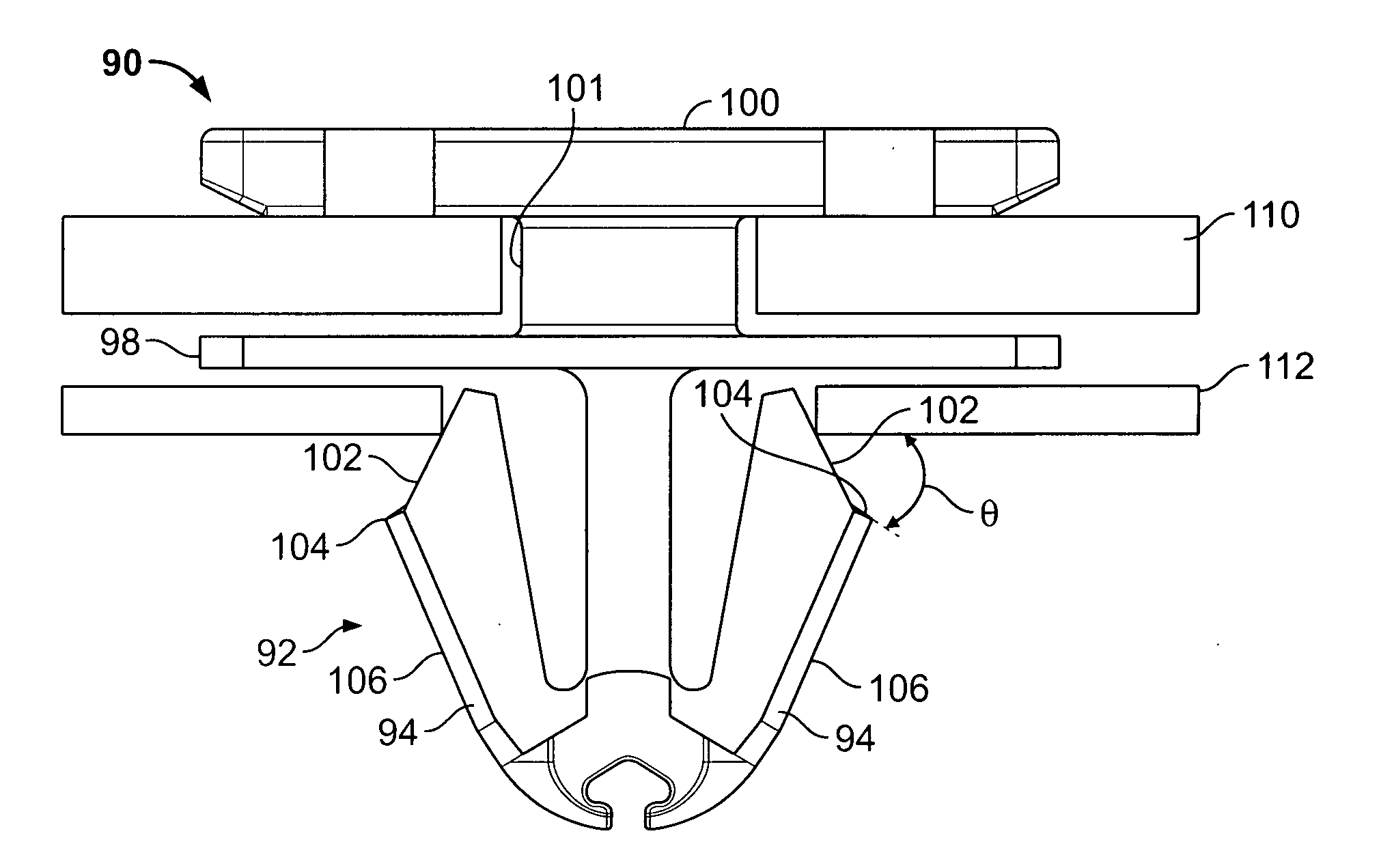
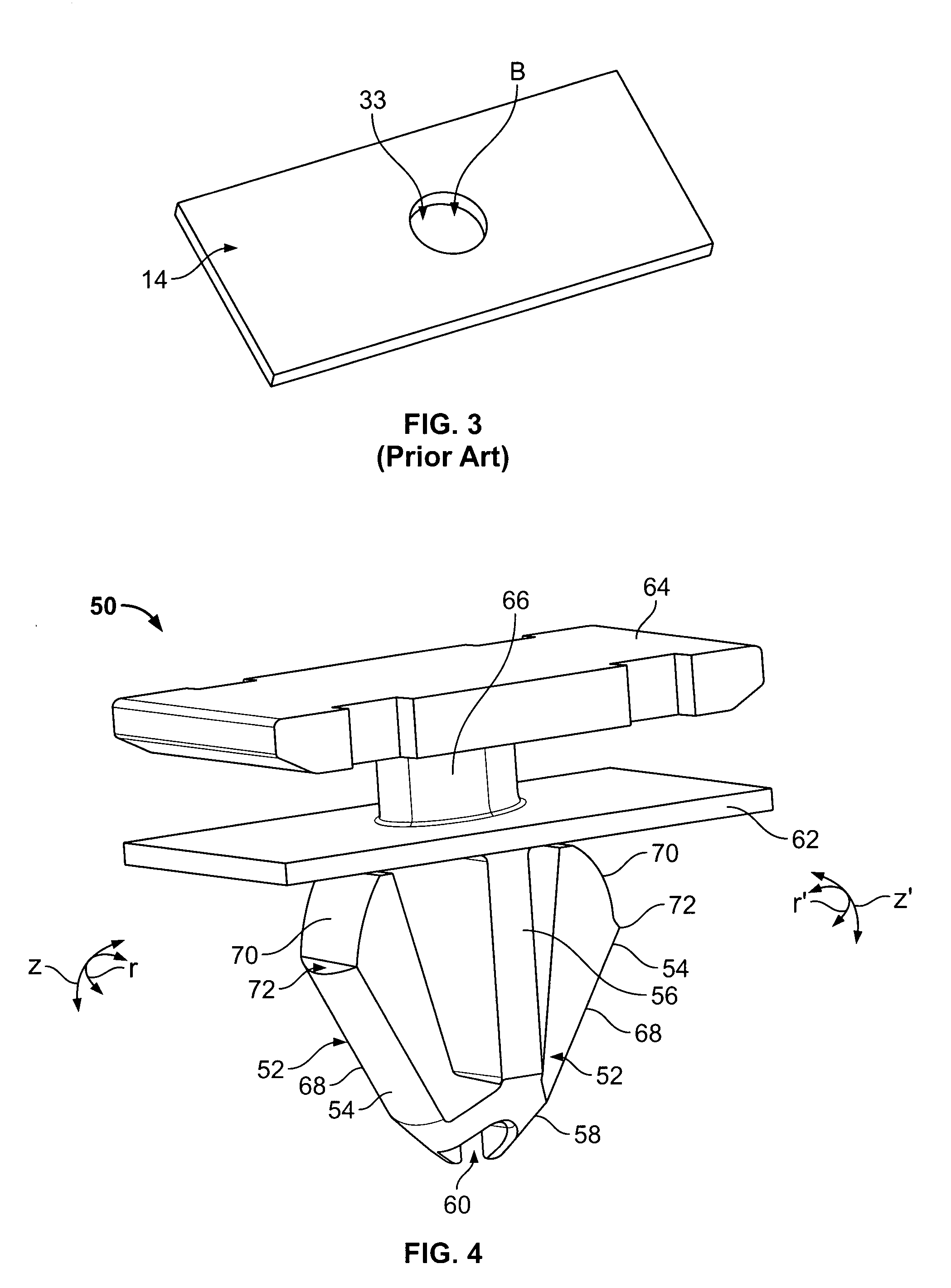
[0031]FIG. 4 illustrates an isometric view of a fastener assembly 50 according to an embodiment of the present invention. FIG. 5 illustrates a front view of the fastener assembly 50. The fastener assembly 50 may be integrally formed and manufactured as a single piece. Further, the fastener assembly 50 may be formed of various materials such as rubber, plastic, or metal. The fastener assembly 50 may also include a foam seal (not shown).

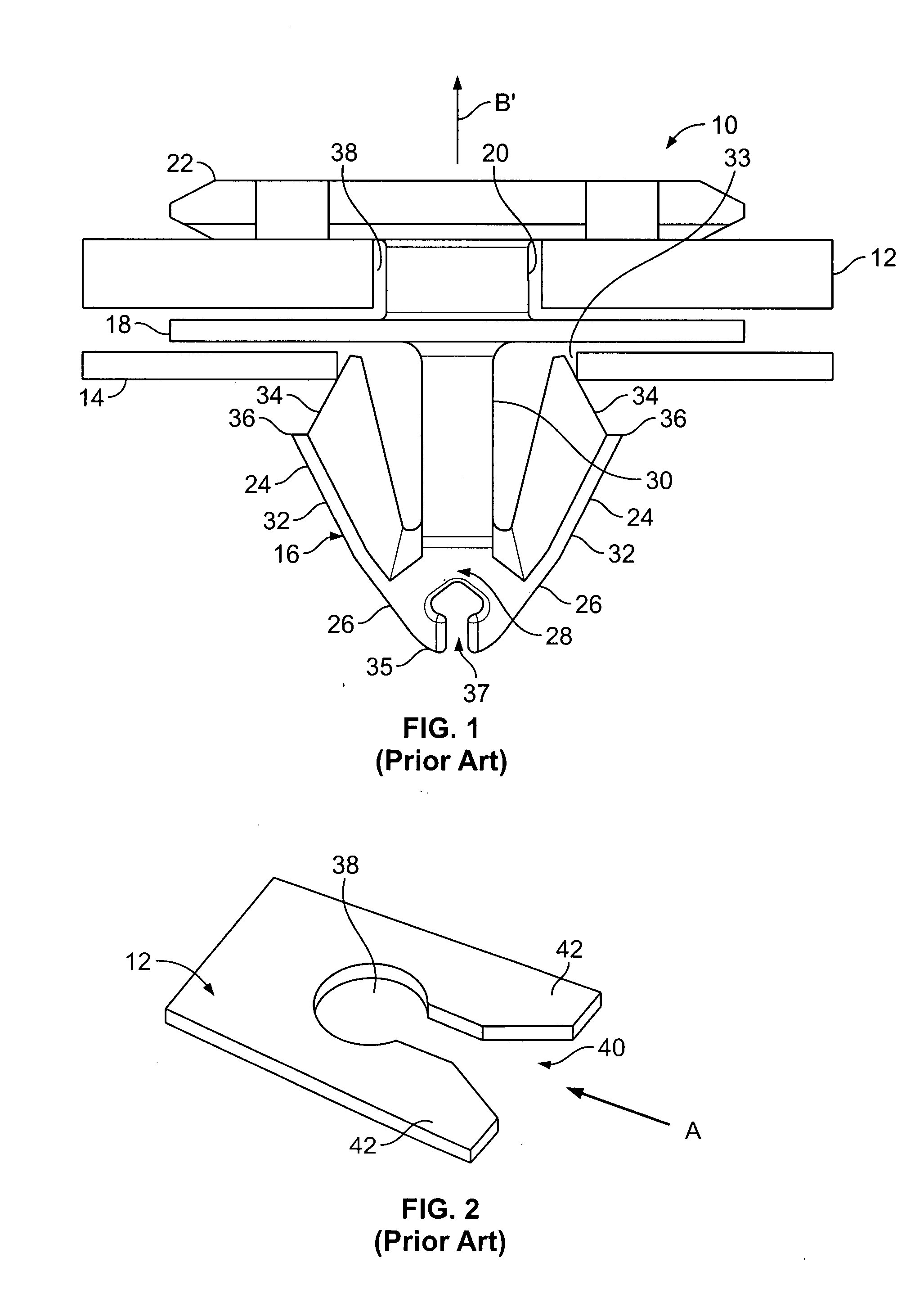
[0032]Referring to FIGS. 4 and 5, the fastener assembly 50 includes similar components as the fastener assembly 10. In particular, the fastener assembly 50 includes a W-shaped base 52 having resilient lateral wings 54 connected to a central post 56 through a distal tip 58 having a central gap 60. The central post 56, the lateral wings 54, and two-stage enter angle of the distal tip 58 assist an operator in finding a location of a hole in a mating panel. That is, the sloped surfaces 53 and 55 of the distal tip 58 allow the fastener assembly 50 to slidab...


PUM


Abstract

A fastener assembly configured to secure a first panel with respect to a second panel includes a base having lateral wings connected to a central post. The lateral wings and the central post converge at a distal tip. Each of the lateral wings includes a first outer surface and a second outer surface, wherein the first outer surface is inwardly angled toward the distal tip. The fastener assembly also includes angled retaining ledges located between the first outer surface and the second outer surface. The angled retaining ledges are canted in a non-parallel fashion with respect to a plane of at least one of the first and second panels. The angled retaining ledges allow for safe and easy removal of the base from at least one of the first and second panels.

Description

RELATED APPLICATIONS[0001]This application relates to and claims priority benefits from U.S. Provisional Patent Application No. 60 / 844,620 entitled “Fastener Assembly,” filed Sep. 14, 2006, which is hereby incorporated by reference in its entirety.FIELD OF THE INVENTION[0002]Embodiments of the present invention generally relate to a fastener configured to connect first and second components together, and more particularly to a fastener configured to connect panels of an automobile assembly to panel molding and trim pieces.BACKGROUND OF THE INVENTION[0003]Various assemblies include panels or objects connected to one another. Automobile assemblies, for example, include various panels and structures connected to other panels or structures, or to the automobile frame itself. In particular, snap-fit assemblies may be used to connect the pieces together. Additionally, a fastener may be preassembled with one of the components or panels, while the second component or panel is connected to t...

Claims


Application Information

Patent Timeline
IPC IPC(8): B62D65/14
CPCB60R13/0206Y10T24/44026Y10T24/309F16B21/086
Inventor SCROGGIE, DEREKOSTERLAND, ROBERTJURILY, BRETT J.
Owner ILLINOIS TOOL WORKS INC
Why Eureka
Try Eureka