

Condenser and radiator of air conditioning refrigeration system
- Summary
- Abstract
- Description
- Claims
- Application Information
AI Technical Summary
Benefits of technology
Problems solved by technology
Method used
Image

Examples
Embodiment Construction
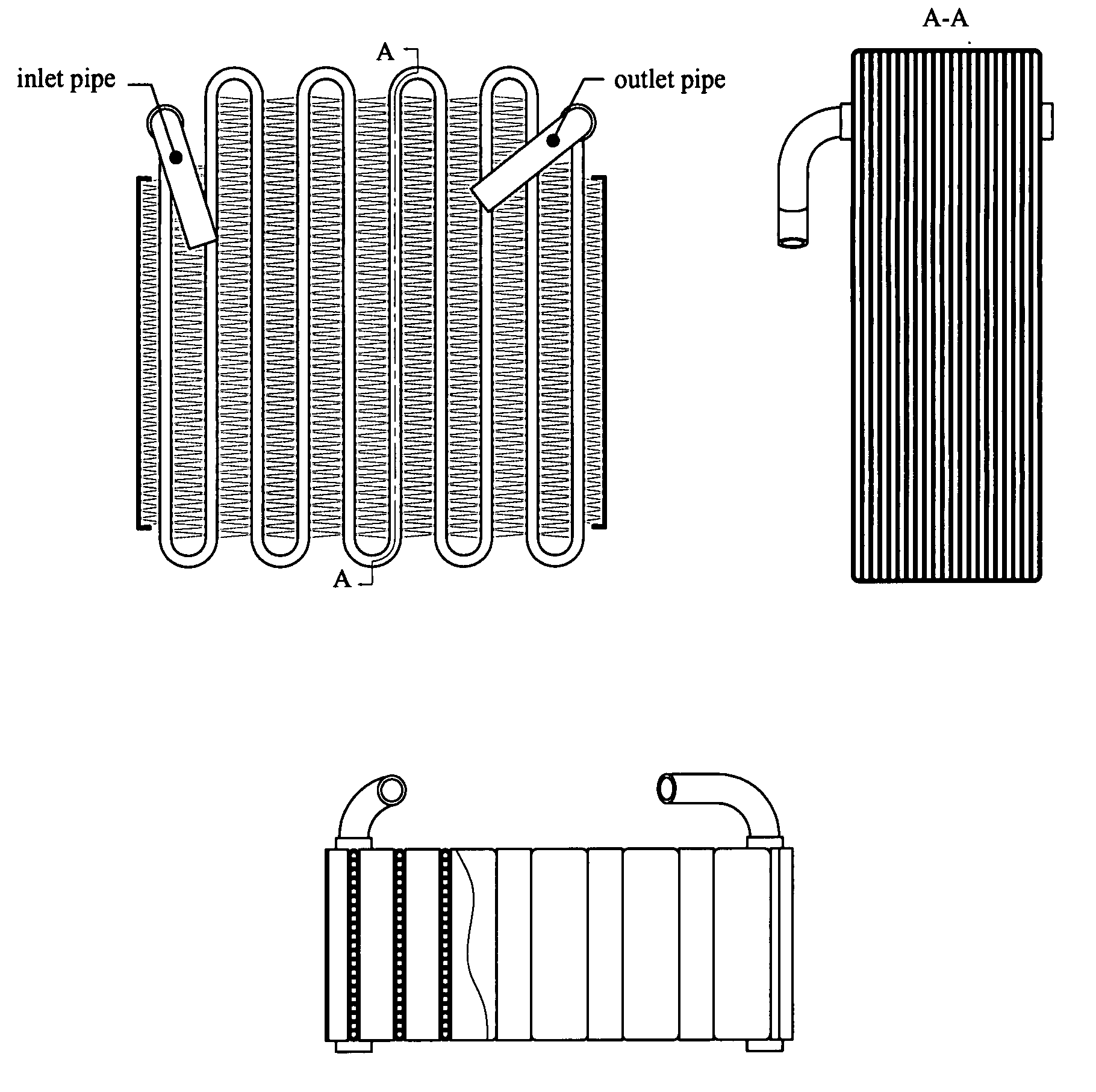
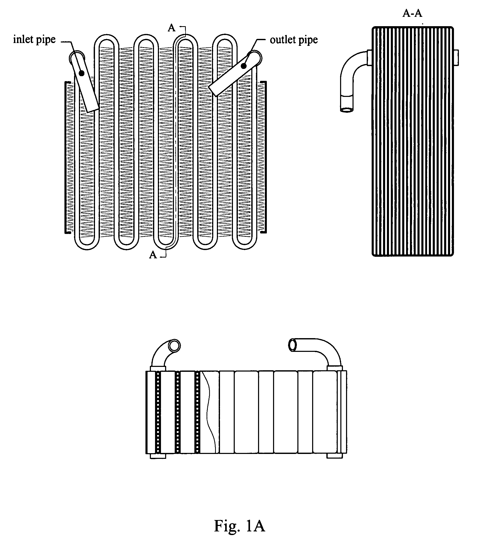
[0042]With reference to the accompanied figures, the embodiments of the present invention will be described in detail as follows. The present invention relates to a condenser and a radiator used in air conditioning refrigeration system. As the structure of the condenser is similar to that of the radiator, the structure of the radiator will be described as an example in the following.
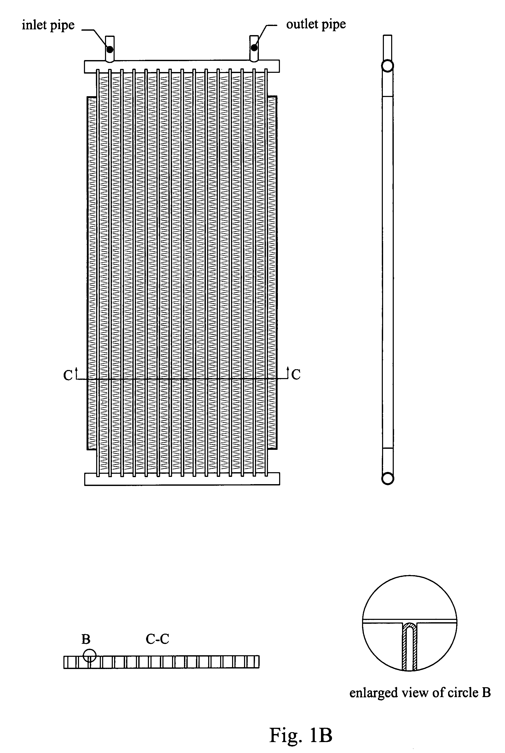
[0043]FIGS. 3-5 show one embodiment of the radiator of the present invention. The radiator 1 comprises a number of radiator units 2, an upper one-way channel 3, a lower one-way channel 4, an inlet port 5 and an outlet port 6. The upper one-way channel 3 is mounted on the upper end of the radiator units 2, and the lower one-way 4 on the lower end thereof. The inlet port 5 and the outlet port 6 are disposed on the two outmost radiator units 2, respectively.
[0044]As shown in FIG. 3, the number of the radiator units is six. However, a single radiator unit together with an inlet port and an outlet port could ...
PUM
 Abstract
Description
Claims
Application Information