Self-regulating turbine

Inactive Publication Date: 2005-11-03
DEUTE ENERGIE HLDG
View PDF5 Cites 0 Cited by
  • Summary
  • Abstract
  • Description
  • Claims
  • Application Information

AI Technical Summary

Benefits of technology

[0034] The absorber tubes lying in or on the absorber surface can be filled with a good gas or steam-permeable and good heat-conducting filler material, such as copper wool, in order to achieve a better transfer of heat from the absorber surf

Problems solved by technology

The known forms of turbines, however, are disadvantageous in terms of the optimal e

Method used


Image

  • Self-regulating turbine
  • Self-regulating turbine
  • Self-regulating turbine

Examples


Example

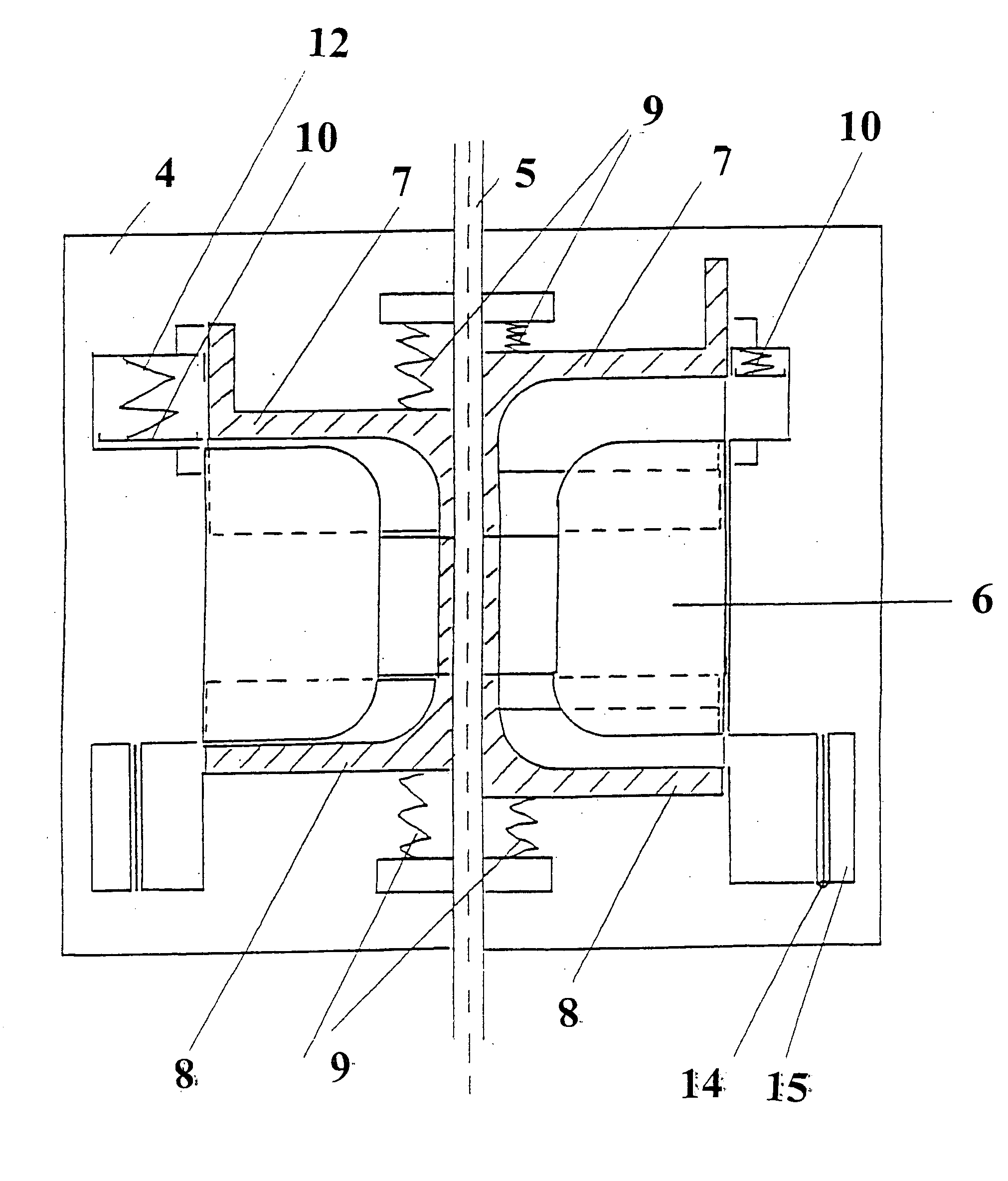
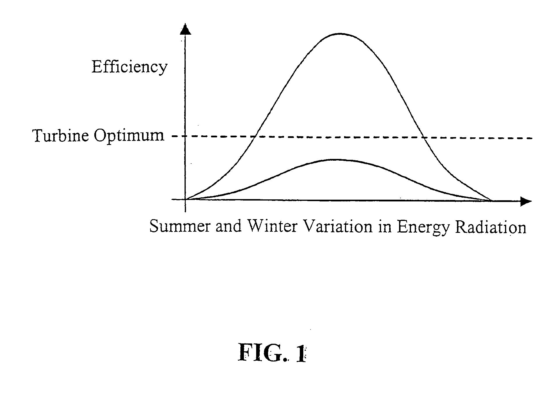
[0053] In one aspect, a turbine is provided with an axial inlet flow and radial outlet flow according to an embodiment of the invention. The turbine is designed for operation with varying gas or steam quantities at varying temperatures or pressures. The flow gap is closed after reaching the rated speed in dependence on the available heated gas or steam quantity or the size of the flow gap between the turbine vanes and / or the turbine blade inclination and / or the length of the turbine vanes is automatically adjusted as a function of pressure and / or temperature and the change in current flow in the generator connected downstream from the turbine is used as an additional regulating quantity for limiting the speed of the turbine.

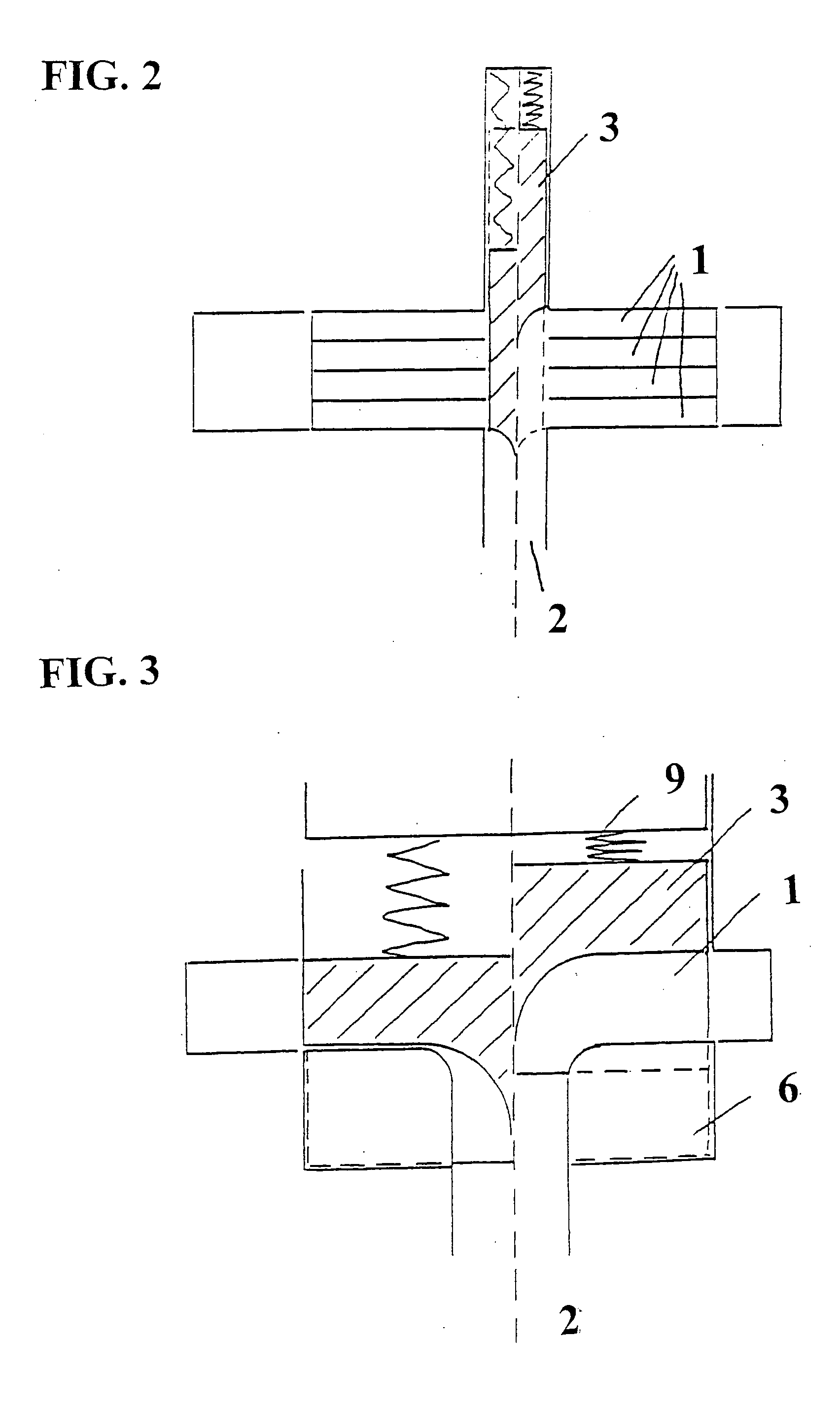
[0054] Referring now in detail to the drawings, FIGS. 2 and 3 show a turbine in which several turbine sets 1 with an axial gas or steam borehole 2 are arranged axially to each other. Each turbine set 1 is arranged on a separating seating disk. In the central gas...


PUM


Abstract

An energy cascade which is preferably fed by solar energy is made from standard solar absorbers including Seebeck elements on the upper end thereof, a self-regulating turbine including a generator arranged downstream and Seebeck elements arranged on the turbine outlet, a heat exchanger for the secondary circuit, and regulating devices for controlling the inner pressure of the primary circuit. The turbine is matched to varying operating conditions by means of suitable measures: matching of the inlet channel, changing turbine blade length for radial turbines, electronic control of the current generated in the generator for rotational speed limitation and a Seebeck heat/current exchanger in the turbine outlet channel.

Description

CROSS REFERENCE TO RELATED APPLICATIONS [0001] This application is a continuation under 35 U.S.C. §120 of International Application No. PCT / DE2003 / 003607, filed on Oct. 30, 2003, which claims priority from German No. 102 51 752.5, filed on Nov. 5, 2002.BACKGROUND OF THE INVENTION [0002] 1. Field of the Invention [0003] The present invention relates to a self-regulating turbine. [0004] 2. The Prior Art [0005] DE 42 00 507 A1 discloses a turbine with very many geometrical adjustment possibilities. These possibilities include adjusting the blade wheel 3a, the flow gap or its size and at the same time the turbine vane length 2 or turbine blade length, and the spiral 14 is not changed automatically by the blade spring 9. [0006] Automatic geometrical alterations are disclosed by the documents U.S. Pat. No. 3,149,820 and U.S. Pat. No. 4,540,337. [0007] These documents represent only a selection from many known technical solutions. [0008] The known design concepts have long experimented wit...

Claims


Application Information

Patent Timeline
IPC IPC(8): F01D5/04F01D17/14
CPCF01D5/043F01D5/048F05D2270/304F01D17/146F01D17/14
Inventor PRIEBE, KLAUS-PETER
Owner DEUTE ENERGIE HLDG
Why Eureka
Try Eureka