Heat exchange tube with inner fins and heat exchanger

A technology of heat exchange tubes and inner fins, which is applied in the field of heat exchange equipment, can solve the problems that the performance of coolers cannot be effectively exerted, the impact of heat exchange performance, and high manufacturing costs, and achieve compact structure, improved reliability, and low manufacturing costs. low effect

Active Publication Date: 2017-06-20
BEIJING U BRIDGE CHAOYANG
View PDF6 Cites 2 Cited by
  • Summary
  • Abstract
  • Description
  • Claims
  • Application Information

AI Technical Summary

Problems solved by technology

This type of heat exchanger is relatively small in size and high in heat exchange efficiency, but its structure is complex and its manufacturing cost is high
[0006] The traditional plate-fin heat exchanger is usually designed with integral fins, and the fins are straight in the axial direction. With the improvement of the engine's performance requirements for the exhaust gas recirculation cooler, in a limited space, the corrugated heat exchanger can be used Integral fins are used to improve heat exchange efficiency, but the spacing of the fins must be continuously reduced to achieve high performance, which may cause blockage between the fins in the case of carbon deposits, so that the performance of the cooler cannot be effectively improved In addition, because there are many contact points between fins and flat tubes or partitions, that is, there are many welding points, failures are prone to occur. In the case of fins falling off, it will also have a greater impact on heat transfer performance.

Method used


Image

  • Heat exchange tube with inner fins and heat exchanger
  • Heat exchange tube with inner fins and heat exchanger
  • Heat exchange tube with inner fins and heat exchanger

Examples


Embodiment 1

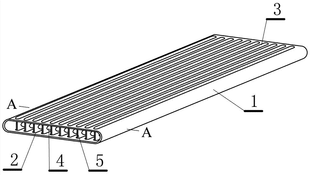
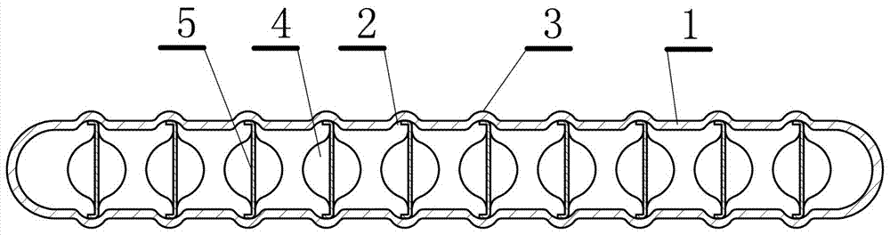
[0041] This embodiment is a heat exchange tube with inner fins, such as figure 1 shown. This embodiment includes: a tube body 1 with a long rectangular cross-section, the upper and lower sides of the tube body are correspondingly provided with a plurality of paired strip-shaped depressions 2 along the fluid movement direction in the tube, and the plurality of strips Shaped depressions form elongated protrusions 3 on the outer surface of the tube; at least one fin 5 with point protrusions or short-line protrusions 4 is connected to the upper and lower corresponding elongated depressions, see figure 2 .

[0042] The shape of the tube body described in this embodiment is similar to a traditional flat tube, and its cross-sectional shape is a rectangle with longer sides, or simply a flat tube with an elongated cross section, such as figure 2 As shown, the two short sides of the rectangle can be straight sides or semi-circular transitions (such as figure 2 The cross-sectional ...

Embodiment 2

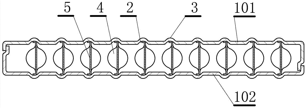
[0059] This embodiment is an improvement of the first embodiment, and is a refinement of the first embodiment on the pipe body. The pipe body described in this embodiment is composed of upper and lower parts 101, 102, as image 3 mentioned.

[0060] In order to facilitate the processing of the pipe body, the present embodiment divides the pipe body into upper and lower parts, and after bending, the bending part is connected to form a whole. That is to say, the pipe body is formed by bending and welding two plates, and has two connection welds. The pipe body designed in this way has very good process performance. The strip-shaped protrusions on the surface of the tube body can be very convenient for punching and forming, and at the same time, it is also convenient for the fins to be conveniently welded in the tube body. The interface of the upper and lower parts of the pipe body can be symmetrically designed on both sides of the pipe body, or as image 3 The tubes in the mi...

Embodiment 3

[0062] This embodiment is an improvement of the above embodiment, and is a refinement of the above embodiment regarding the pipe body. The outer surface of the tube described in this embodiment is provided with a supporting protrusion 103, such as Figure 4 shown.

[0063] When the heat exchange tube is fed with high-temperature gas during work, the tube itself will expand thermally, which will reduce the distance between the heat exchange tubes, which is very harmful. The smaller the distance between the heat exchange tubes, the narrower the circulation channel of the coolant, which affects the efficiency of the coolant to remove heat. In order to keep the distance between the heat exchange tubes constant, this embodiment sets point-shaped or short-line protrusions outside the tube body, and the protrusions between two adjacent heat exchange tubes interact to effectively place the tube body Close to each other and maintain a distance between each other.


PUM


Abstract

The invention relates to a heat exchange tube with inner fins and a heat exchanger. The heat exchange tube comprises a tube body, wherein the section of the tube body is in a strip rectangular shape. Multiple paired strip-shaped concave portions in the motion direction of fluid in the tube are correspondingly arranged on the upper face and the lower face in the tube body, and the multiple strip-shaped concave portions form strip-shaped protrusions on the outer surface of the tube body. At least one fin with point protrusions or short-line-shaped protrusions is connected in the up-and-down corresponding strip-shaped concave portions. According to the heat exchange tube, by means of the manner of arranging the cooling fins in the heat exchange tube, a heat transfer face is increased, the fins serve as a secondary heat transfer face, hot air flow heats the fins, and heat on the fins is transmitted into cooling liquid through the strip-shaped protrusions while being transmitted to the surface of the heat exchange tube through the strip-shaped protrusions on the heat exchange tube; and the point-shaped or short-line-shaped protrusions arranged on the fins can stir and disturb flowing air, carbon deposition is avoided, and the heat exchange efficiency is improved. Due to the fact that the tube body and the fins can be produced in a stamped manner, on the premise of meeting the heat exchange requirement, fin arrangement can be reduced, the fins are reduced, welding points are few, reliability is improved, welding is quite convenient, the heat exchange tube is suitable for mass production, and the beneficial effect of being low in manufacturing cost is achieved.

Description

technical field [0001] The invention relates to a heat exchange tube and a heat exchanger with inner fins, which are equipment used in automobile engines, equipment used in engine facilities, and heat exchange equipment used in engine EGR systems. equipment. Background technique [0002] For heat exchangers, improving heat exchange efficiency and reducing the volume of heat exchangers has always been the direction and subject of research in the industry, especially for heat exchangers applied to automobile engines, maintaining or increasing heat exchange efficiency as much as possible Under the premise, it is more important to reduce the volume of the heat exchanger. At the same time, it is necessary to consider the technological performance of the product and whether it meets the needs of mass production. [0003] There are basically two types of traditional heat exchangers: plate-fin heat exchangers and shell-and-tube heat exchangers, each of which has its own advantages...

Claims


Application Information

Patent Timeline
Patent Type & Authority Applications(China)
IPC IPC(8): F28F1/02F28F1/40F28D7/16
CPCF28D7/16F28F1/022F28F1/40
Inventor 景建周汤俊洁沈董浩张军强
Owner BEIJING U BRIDGE CHAOYANG
Why Eureka
Try Eureka