Pipe-plate type heat exchanger adopting foamy copper material

A technology of heat exchanger and copper foam, which is applied in the direction of heat exchange equipment, heat exchanger type, indirect heat exchanger, etc., can solve the problems of low pressure bearing capacity, large floor area, and low heat transfer efficiency, and achieve full Utilization, compact structure, small size effect

Inactive Publication Date: 2018-10-23
SHANGHAI UNIVERSITY OF ELECTRIC POWER
View PDF11 Cites 1 Cited by
  • Summary
  • Abstract
  • Description
  • Claims
  • Application Information

AI Technical Summary

Problems solved by technology

[0003] The traditional shell-and-tube heat exchanger has simple structure, mature technology, and wide application, but has disadvantages such as low heat transfer efficiency and large

Method used


Image

  • Pipe-plate type heat exchanger adopting foamy copper material
  • Pipe-plate type heat exchanger adopting foamy copper material
  • Pipe-plate type heat exchanger adopting foamy copper material

Examples


example

[0026] (1) Recovery of waste heat from flue gas in power plants (cooling liquid in this case is cooling water).

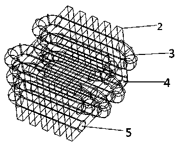
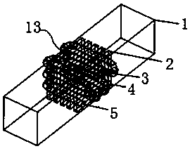
[0027] In order to prevent the dust in the flue gas from clogging the channel, the figure 1 The heat exchanger shown is placed after the dust collector. The cooling water is passed through the nozzle water inlet 4, and the cooling water flows along the serpentine pipe. Since the entire cooling water pipe is interspersed and distributed in the heat exchange section, a part of the pipe passes through the flue gas flowing in the gap between the foamed copper plates. Direct heat exchange, part of the heat exchange with the copper foam attached to it, and finally flow out from the tube outlet 5 located below.

[0028] The flue gas flows in from one end of the horizontal flue, and flows through the gap between the cooling water pipe and the foam copper plate surface when passing through the heat exchange section. Part of the heat in the flue gas exchanges heat with the ...


PUM

PropertyMeasurementUnit
Average pore sizeaaaaaaaaaa

Abstract

The invention relates to a pipe-plate type heat exchanger adopting a foamy copper material. Multiple foamy copper plates are placed in parallel at intervals, and an S-shaped cooling water pipeline alternately crosses back and forth between the foamy copper plates, so that the foamy copper heat exchanger is formed and is arranged in a flue shell. When a flue gas flows in from one end of a flue andpasses through the foamy copper heat exchanger in the middle, the flue gas penetrates through the gaps between the foamy copper plates and the S-shaped cooling water pipe, one part of heat in the flue gas directly exchanges heat through the S-shaped cooling water pipe, and the other part of heat in the flue gas is transferred to cooling water through the foamy copper plates or stored in gap spaces of the foamy copper plates so as to be absorbed by cooling water; and the low-temperature flue gas subjected to heat exchange with the cooling water flows out from the other end of the flue. The heat exchanger is compact in structure, small in volume and high in heat exchange efficiency, and not only can be applied to recycling flue gas waste heat and water, but also can be applied to recyclingwater in other waste heat and waste gases.

Description

technical field [0001] The invention relates to a device for recovering waste heat and water in flue gas, in particular to a device for recovering waste heat and water in power plant boiler flue gas. Background technique [0002] With the development of society and the progress of industry, the energy crisis has become a major problem that all countries in the world must face and solve. This makes energy saving and emission reduction more important. The known heat exchanger equipment has problems such as low efficiency or large volume due to material and technical reasons. However, with the improvement of technology and level in recent years, various new materials have been used After being developed, these materials often have characteristics that other materials do not have, which provides conditions for the development of new heat exchanger equipment. [0003] The traditional shell-and-tube heat exchanger has simple structure, mature technology, and wide application, but...

Claims


Application Information

Patent Timeline
IPC IPC(8): F28D7/08F28F21/08F28F27/00
CPCF28D7/082F28F21/085F28F27/00
Inventor 范鑫磊姜未汀涂钊潘卫国汪腊珍葛洋陈孝青葛帅
Owner SHANGHAI UNIVERSITY OF ELECTRIC POWER
Why Eureka
Try Eureka