Dissolvable downhole trigger device

a trigger device and dissolvable technology, applied in the direction of fluid removal, borehole/well accessories, sealing/packing, etc., can solve the problem that the retaining member is no longer able to prevent the movement of the actuating member, and achieve the effect of reducing the cost associated

Active Publication Date: 2008-03-20
BAKER HUGHES INC
View PDF28 Cites 157 Cited by
  • Summary
  • Abstract
  • Description
  • Claims
  • Application Information

AI Technical Summary

Benefits of technology

[0020]The trigger devices and methods disclosed herein have one or more of the following advantages: permitting customization of the trigger device such that the amount of time for the trigger device to be activated is pre-determined; pe

Problems solved by technology

Upon dissolution of the dissolving material, the retaining member is

Method used


Image

  • Dissolvable downhole trigger device
  • Dissolvable downhole trigger device
  • Dissolvable downhole trigger device

Examples


Embodiment Construction

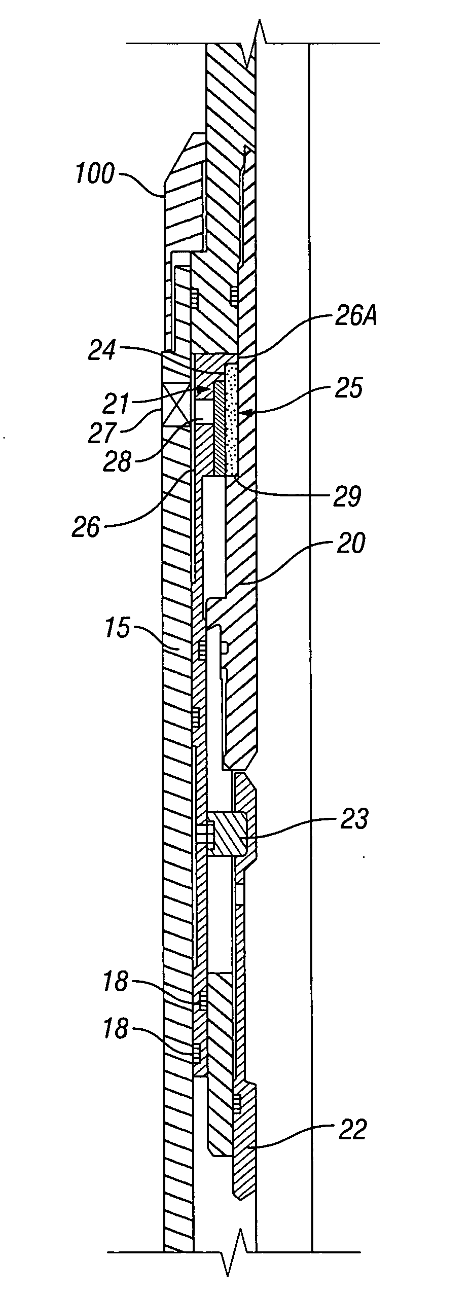
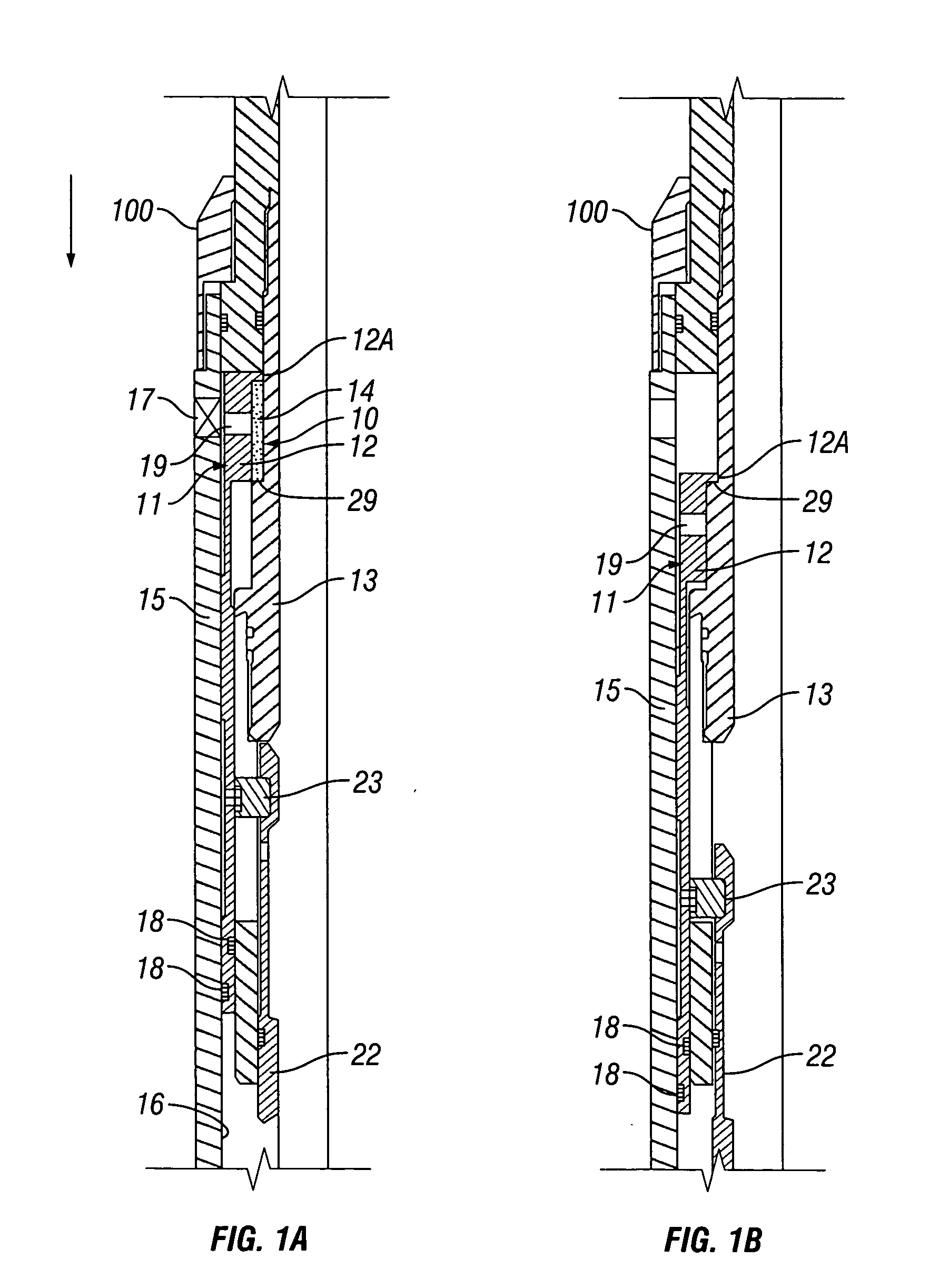
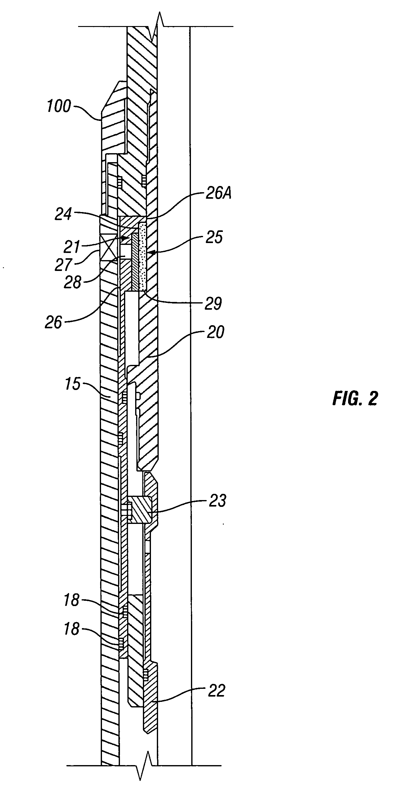
[0029]Referring to FIGS. 1A and 1B, in one embodiment, trigger device 10 is included as part of downhole tool 100. Downhole tool 100 is lowered on a string of conduit into the well and may be used for setting a packer, a bridge plug, or various other functions. Trigger device 10 has actuating member 11, which as shown in FIGS. 1A and 1B, is piston 12. Generally, movement of actuating member 11, e.g., piston 12, sets downhole tool after it is properly located in a well (not shown). As shown in FIG. 1A, piston 12 is in its initial or “run-in” position. The initial position is the position prior to actuation of downhole tool 100. FIG. 1B shows piston 12 in the actuated position.

[0030]In this example, piston 12 comprises a sleeve carried in an annular chamber around a central mandrel assembly 13 of tool 100 and within a housing 15 of tool 100. Piston 12 has inner and outer seals 18 that slidably engage mandrel assembly 13 and the inner side wall of housing 16 when actuated. Piston 12 is...


PUM


Abstract

A trigger device for setting a downhole tool is disclosed. The trigger device includes a retaining member that prevents the downhole tool from setting until it is properly positioned within the well. Regardless of the type of downhole tool or the type of trigger device, the retaining member includes a dissolvable material that dissolves when contacted by a solvent. The dissolvable material is preferably one that dissolves at a known rate so that the amount of time necessary for the downhole tool to set is pre-determined. Preferably, the solvent is a water-based or hydrocarbon-based drilling fluid or mud.

Description

BACKGROUND[0001]1. Field of Invention[0002]The present invention is directed to trigger devices for actuating downhole tools and, in particular, trigger devices having a dissolvable material such that when the dissolvable material dissolves, the trigger device is activated and the downhole tool is actuated.[0003]2. Description of Art[0004]Some downhole tools need to be retained in an unset position until properly placed in the well. It is only when they are properly located within the well that the downhole tool is set. Such downhole tools in the past have had trigger mechanisms that are retained in an immovable position while the downhole tool is being “run” into the well and properly placed within the well. One prior technique for holding the trigger mechanism immobile until the downhole tool is properly placed in the well involves disabling the trigger with a mechanical device that is held against movement by a Kevlar® high strength fiber and an associated electrically powered he...

Claims


Application Information

Patent Timeline
IPC IPC(8): E21B29/00
CPCE21B23/00
Inventor XU, YANG
Owner BAKER HUGHES INC
Why Eureka
Try Eureka