Supercharge Your Innovation With Domain-Expert AI Agents!

Solenoid Actuated Valve with a Damping Device

a technology of damping device and solenoid, which is applied in the direction of valve operating means/releasing devices, valve details, engine components, etc., can solve the problems of inapplicability of damper, excessive wear or even breakage of sleeve, etc., and achieve the effect of damping movement of parts

Inactive Publication Date: 2008-03-20
DANFOSS AS
View PDF25 Cites 12 Cited by
  • Summary
  • Abstract
  • Description
  • Claims
  • Application Information

AI Technical Summary

Benefits of technology

[0010] The valve may be associated with, or form as an integral part, a solenoid with a yoke. In order to improve the force of attraction, it is an advantage to arrange the yoke adjacent the first or second part whereby the first or second part can cooperate with the yoke to form a substantially uninterrupted path for the magnetic flux from the yoke to at least one of the first and the second part. An opposite end of the yoke can be located adjacent the plunger, thereby creating a dosed loop extending through the yoke and through the plunger and the second part. In this arrangement, the first part may also be made from a magnetically conductive material and form path for the flux in the loop.
[0011] The elastically deformable member may comprise a resilient polymeric material or a spring, e.g. a spring made from a metallic material, e.g. a disc spring. In particular, the elastically deformable member may be constituted by an O-ring. In that respect, a preferred material converts during deformation as much of the energy as possible to internal resistance, e.g. to heat, and as little energy as possible to recoil. For that purpose, the elastically deformable member could e.g. be made from a fluoro elastomer, FKM or from similar polymeric materials. To enable evacuation of the area around the elastically deformable member, the member could be located in a space between the first and the second parts, the space being in fluid communication with the conduit or in fluid communication with one of the first and second compartments.
[0015] an elastically deformable member arranged between the first and second parts to dampen movement of the parts relative to each other,

Problems solved by technology

As a result, noise, excessive wear or even breakage of the sleeve is sometimes experienced.
Also in this design, a gap of a non-magnetic media, i.e. the rubber element, is created, and therefore also this design is inappropriate with respect to the desire of establishing a strong force of attraction between the top part and the plunger.
In this attempt to alleviate the impact between a movable plunger and adjacent elements without interrupting the path of the magnetic flux, the damper has, however, become inapplicable e.g. for vacuum systems or high vacuum systems wherein evacuation of the valve is required.

Method used


Image

  • Solenoid Actuated Valve with a Damping Device
  • Solenoid Actuated Valve with a Damping Device
  • Solenoid Actuated Valve with a Damping Device

Examples


Embodiment Construction

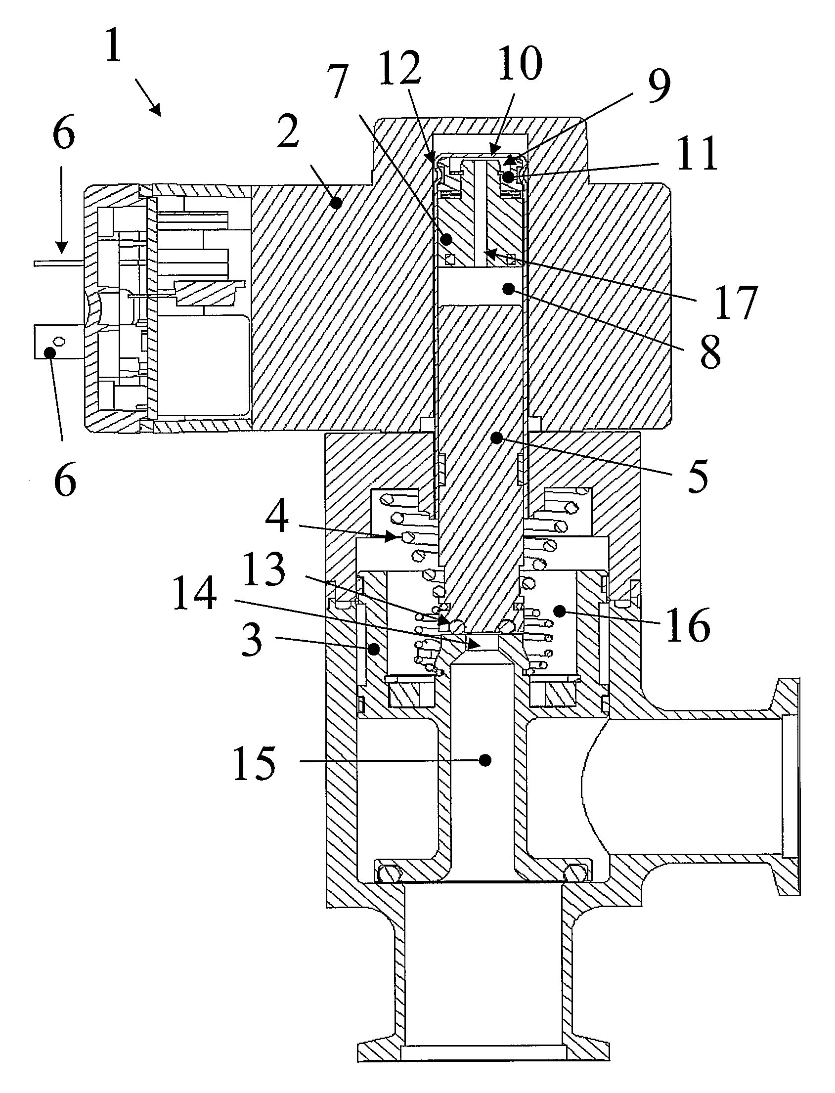
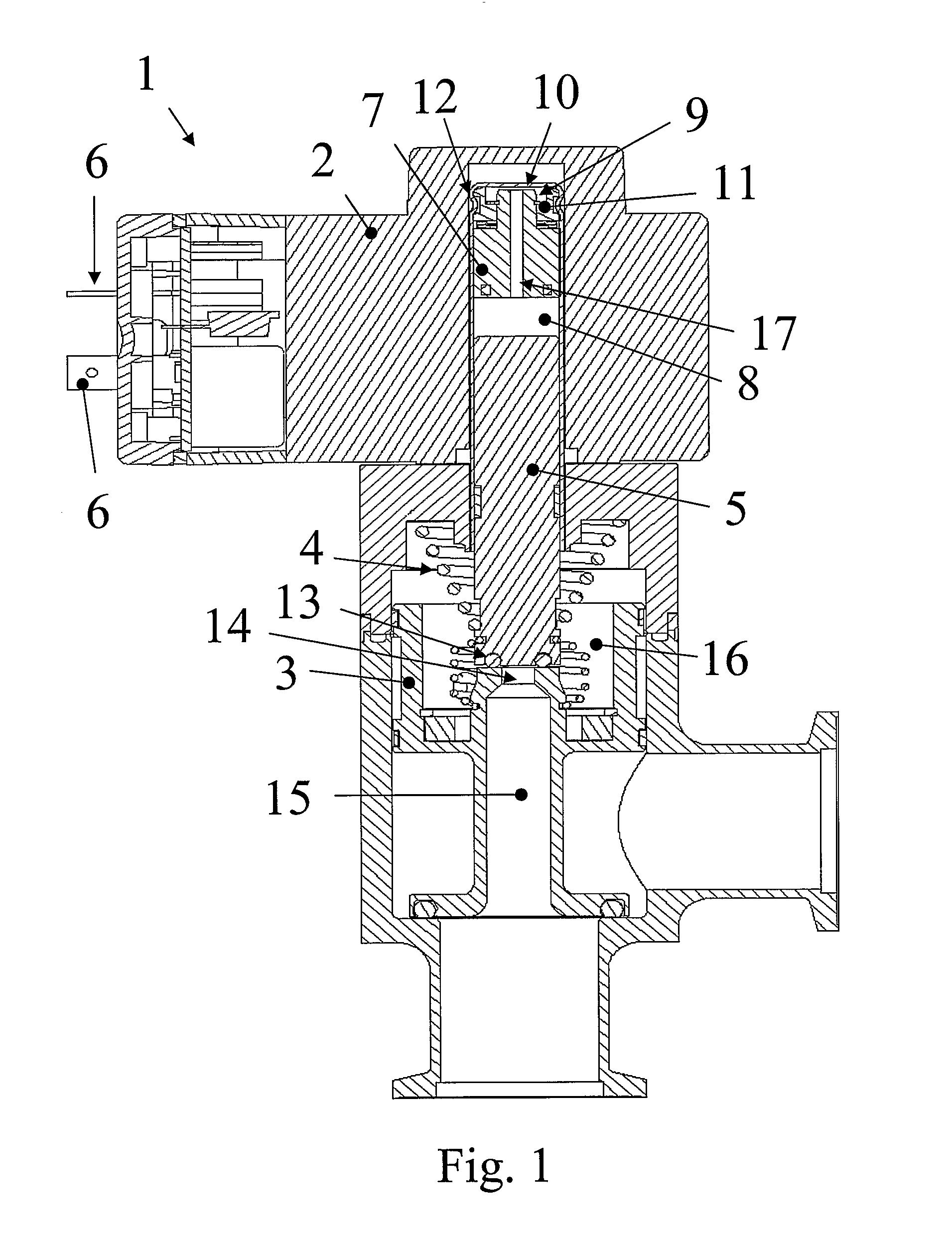
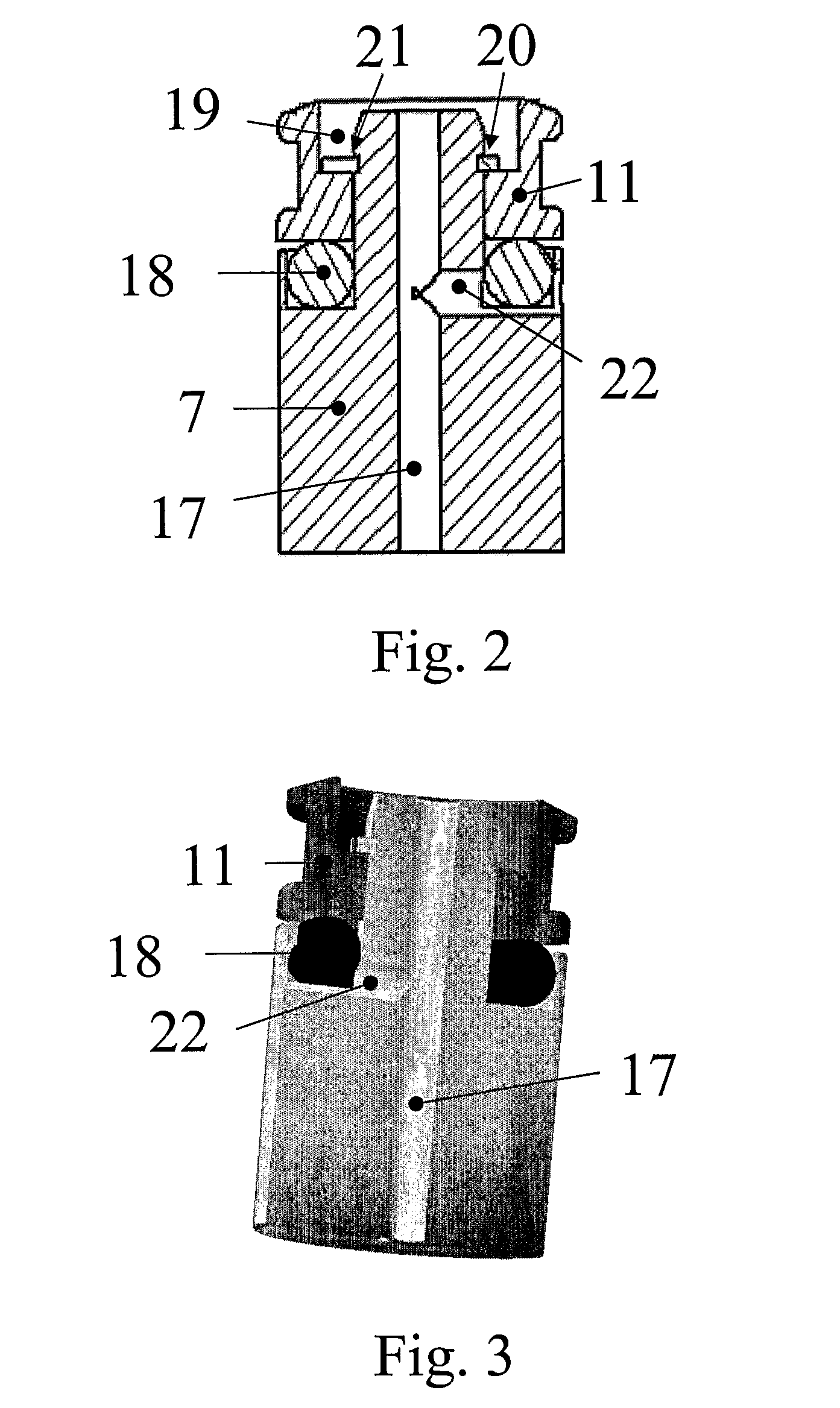
[0026]FIG. 1 shows a valve 1 for a high vacuum system and comprising a solenoid 2 applied to operate on the closure member 3 against the force from the spring 4 to shift the closure member from its dosed position of rest. To move the closure member, the valve comprises a plunger 5 which is actuated magnetically via the solenoid. The solenoid is energised by an electrical current via the connectors 6. The travel of the plunger is limited in one direction by the closure member and in the opposite direction by a second part 7 of the damping device. The damping device is located in a sleeve to separate a first compartment 8 of the sleeve from a second compartment 9 of the sleeve. The second compartment is sealed upwardly by the end part 10 of the sleeve. The damping device, which is shown in further details in FIG. 2, further comprises a first part 11 being attached in the sleeve by a bead of the sleeve which engages a circumferentially extending recess 12 in the first part. The first p...


PUM


Abstract

The invention provides a solenoid actuated valve with a plunger which moves in a sleeve under influence of a magnetic field from the solenoid and further comprising a damping device for reducing noise and wear caused by the plunger when it bounces against a top part located in the sleeve. The damping device comprises a first part which forms the limit of the travel of the plunger and another part which is allowed to move relative to the first part in a dampened movement. To enable application in a vacuum system, the damping device comprises a conduit which allows evacuation of a chamber confined between one end of the sleeve and the damping device. The invention further provides a damper for a solenoid actuated valve.

Description

CROSS REFERENCE TO RELATED APPLICATIONS [0001] This application is entitled to the benefit of and incorporates by reference essential subject matter disclosed in International Patent Application No. PCT / DK2005 / 000574 filed on Sep. 9, 2005 and Danish Patent Application No. PA 2004 01373 filed Sep. 10, 2004.FIELD OF THE INVENTION [0002] The invention relates to solenoid actuated valve with a damping device to reduce noise, wear, strain or breakage of a plunger guide sleeve for a solenoid actuated valve. In particular, the invention relates to a solenoid actuated valve comprising a plunger guide sleeve, a plunger movably arranged in the sleeve, and a damping device located in the sleeve to separate a first compartment of the sleeve from a second compartment of the sleeve. The damping device comprises a first part being attached in the sleeve, a second part joined to the first part in a connection allowing the second part to move relative to the first part, and an elastically deformable...

Claims


Application Information

Patent Timeline
IPC IPC(8): F16K31/06
CPCF16K31/0689F16K51/02F16K31/0693
Inventor PETERSEN, HANS KURT
Owner DANFOSS AS
Features
  • R&D
  • Intellectual Property
  • Life Sciences
  • Materials
  • Tech Scout
  • Unparalleled Data Quality
  • Higher Quality Content
  • 60% Fewer Hallucinations
Learn More