Automatic video format identification system

a video format and video technology, applied in the field of communication systems, can solve the problems of inability to accurately convey signals, loss of most physical devices, and and achieve the effect of reducing the loss of “cable insertion” loss, and reducing the loss of transmission cables of longer length

Inactive Publication Date: 2008-03-20
RGB SYST INC
View PDF24 Cites 10 Cited by
  • Summary
  • Abstract
  • Description
  • Claims
  • Application Information

AI Technical Summary

Problems solved by technology

The cable may not accurately convey the signals because of losses which accumulate along the cable path.
These losses are primarily due to the physical characteristics of the transmission cable and sometimes due to imperfections in the cable construction.
The imperfections may not necessarily be due to manufacturing deficiencies, but may also be due to the fact that a cable is a physical device and most physical devices exhibit some losses when a signal is conveyed through them.
Thus, longer length transmission cables tend to exhibit more loss (also known as “cable insertion” loss) than shorter length cables.
However, coaxial cables are more expensive and difficult to install when compared to twisted pair cables.
Historically, the significant differences between coaxial and twisted pair cables limited twisted pair cables to transmission of low-resolution video (i.e., less than 10 MHz) signals.
However, the specifications they are made to, the materials used to make them, and the requirements to connect them, become more and more critical as data rates increase.

Method used


Image

  • Automatic video format identification system
  • Automatic video format identification system
  • Automatic video format identification system

Examples


Embodiment Construction

[0041] The detailed description set forth below in connection with the appended drawings is intended as a description of illustrated exemplary embodiments and is not intended to represent the only forms in which these embodiments may be constructed and / or utilized. The description sets forth the functions and sequence of steps for constructing and operating the present invention in connection with the illustrated embodiments. However, it is to be understood that the same or equivalent functions and / or sequences may be accomplished by different embodiments that are also intended to be encompassed within the spirit and scope of the present invention.

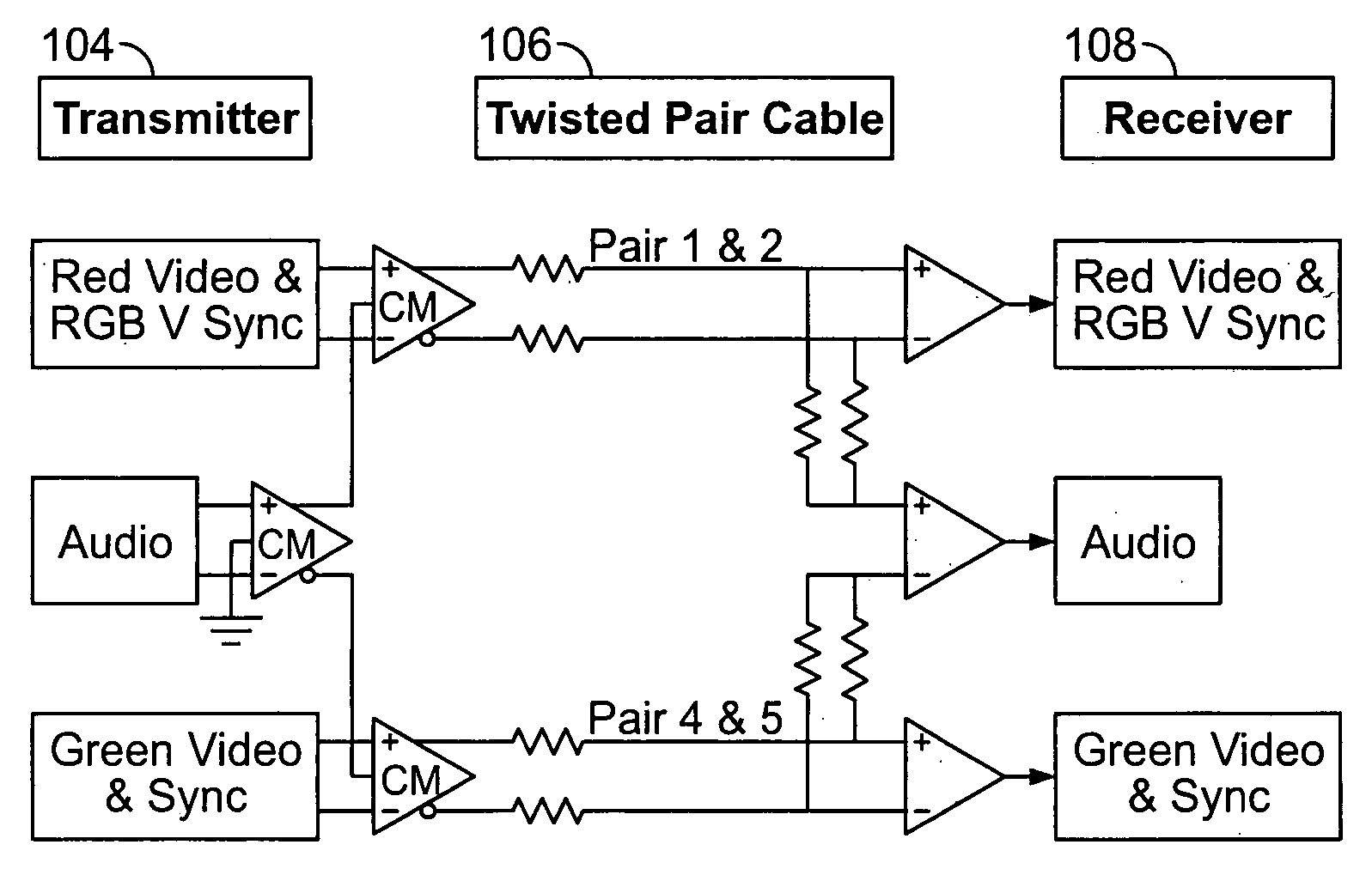
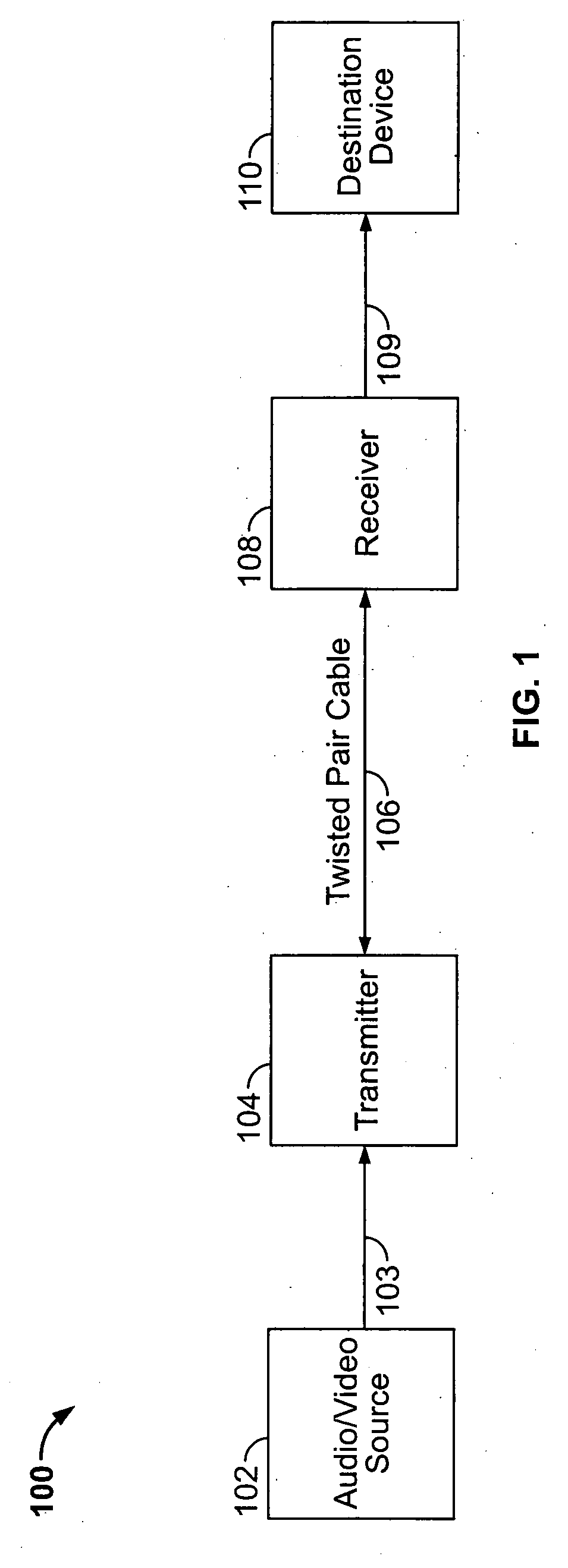
[0042] Some embodiments of the present invention will be described in detail with reference to an automatic video format identification system, as generally depicted in reference to FIGS. 1-22. Additional embodiments, features and / or advantages of the invention will become apparent from the ensuing description or may be learned by practic...


PUM


Abstract

A video format identification system includes a master clock circuit which provides timing and counting signals, a synchronization activity detector operatively coupled to the master clock circuit, and a synchronization width qualifier configured to filter out noise or reference burst signals from showing up as sync signals. The system also includes a synchronization detector which regulates the rate of the incoming sync signal, a color burst sampler providing a window for sampling a reference color burst after the sync signal has occurred, and a color burst detector which looks for at least three transitions from a burst signal before it qualifies the as an appropriate reference color burst. A format sample timer generates sample clock signals. A format sample counter produces “take format” signals which are utilized by a set of format counter. The system further includes a video format identifier which enables a particular video format to be directed to a respective video connector.

Description

FIELD OF THE INVENTION [0001] The present invention relates to communication systems. More specifically, the invention relates to an automatic video format identification system. BACKGROUND [0002] Transmission cables are used to convey electronic signals from a source device to a destination device, e.g., a display terminal. The cable may not accurately convey the signals because of losses which accumulate along the cable path. These losses are primarily due to the physical characteristics of the transmission cable and sometimes due to imperfections in the cable construction. The imperfections may not necessarily be due to manufacturing deficiencies, but may also be due to the fact that a cable is a physical device and most physical devices exhibit some losses when a signal is conveyed through them. Thus, longer length transmission cables tend to exhibit more loss (also known as “cable insertion” loss) than shorter length cables. A length limit exists for each transmission cable med...

Claims


Application Information

Patent Timeline
Patent Type & Authority Applications(United States)
IPC IPC(8): H04N7/04
CPCH04N7/0102
Inventor HALL, RAYMOND
Owner RGB SYST INC
Why Eureka
Try Eureka