Video signal generator generating monochrome signal without color noise

Inactive Publication Date: 2006-04-27
LAPIS SEMICON CO LTD
View PDF16 Cites 0 Cited by
  • Summary
  • Abstract
  • Description
  • Claims
  • Application Information

AI Technical Summary

Benefits of technology

[0014] By use of a simple selector, the invented video signal generator can output an analog composite video signal that, when representing a color picture, includes the normal color burst and luminance and chrominance components, and when representing monochrome picture, includes only the luminance compon

Problems solved by technology

A problem with the conventional analog composite video signal is that when the signal represents a monochrome picture, even though there should be no chrominance component, the color subcarrier in the received signal is normally modulated to some extent by various forms of color noise.
This method could be adapted for use with analog video signals, but it suffers from problems of complexity and inconvenience.
A receiving device lacking this type of vi

Method used


Image

  • Video signal generator generating monochrome signal without color noise
  • Video signal generator generating monochrome signal without color noise
  • Video signal generator generating monochrome signal without color noise

Examples


first embodiment

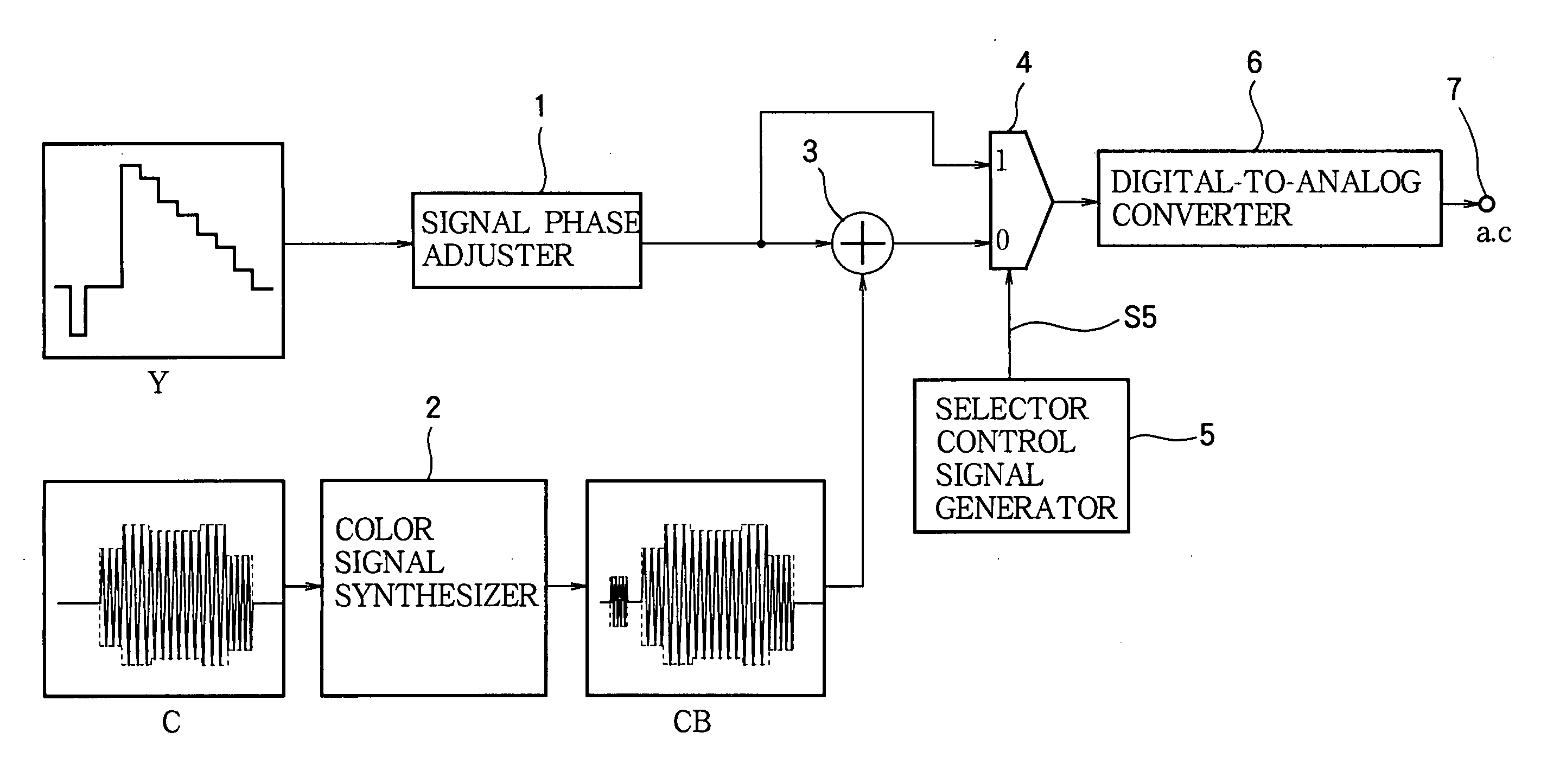
[0029] Referring to FIG. 3, the first embodiment is a video signal generator that receives a digital luminance signal Y and a digital chrominance signal C, the digital chrominance signal C including of a pair of color difference signals. A signal phase adjuster 1 comprising, for example, a plurality of flip-flops delays the digital luminance signal Y to bring it into phase with the digital chrominance signal with which it will be combined. A color burst signal synthesizer 2 generates a digital color burst signal, adds the color burst to the digital chrominance signal C, and modulates the sum onto a subcarrier signal to generate a modulated digital chrominance signal CB including a modulated color burst. An adder 3 adds the delayed digital luminance signal to the modulated digital chrominance signal. The output terminal of the adder 3 is connected to one input terminal of a selector 4; this input terminal is marked ‘1’ in the drawing and will be referred to below as the logical one i...

second embodiment

[0041] Referring to FIG. 8, the second embodiment is a video signal generator that differs from the video signal generator in the first embodiment in having a color signal decision circuit 5A in place of the selector control signal generator 5 in FIG. 3. Other structures are the same as in the first embodiment.

[0042] The color signal decision circuit 5A decides, by comparing the average amplitude of the chrominance signal CB with a threshold, for example, whether the chrominance signal CB represents a color video signal (if the average amplitude exceeds the threshold) or a monochrome video signal (if the average amplitude is less than the threshold) Instead of average amplitude, some other measure of signal strength, such as average power level or average modulation degree, may be used. The decision result is output as a control signal S5 (logical one for a monochrome signal; logical zero for a color video signal) that controls the selector 4 as described in the first embodiment.

[...

third embodiment

[0051] Referring to FIG. 10, the third embodiment is a video signal generator 100 that comprises the circuit in FIG. 3 or FIG. 8 and has, in addition to the composite video output terminal 7, an S-video connector with separate terminals 101, 102 for the luminance signal (output at terminal 101) and the chrominance signal (output at terminal 102). Terminal 101 is connected through an A / D converter (not shown) to the output terminal of the signal phase adjuster 1 in FIG. 3 or 8. Terminal 102 is connected through another A / D converter (not shown) to the output terminal of the color burst signal synthesizer 2. The waveforms 103 produced at the three output terminals 7, 101, 102 for a color picture differ as illustrated in FIG. 10 from the waveforms 104 produced for a monochrome picture. For a monochrome picture, the receiving device can obtain the same signal from either the composite video output terminal 7 or the S-video luminance output terminal 101.


PUM


Abstract

A video signal generator adds a digital luminance signal to a digital chrominance signal including a color burst to obtain a digital composite video signal. A selector selects the digital luminance signal for a monochrome picture and the digital composite video signal for a color picture. A digital-to-analog converter converts the selected signal to an analog signal, which is output from a composite video output terminal. The selection may be made by comparing the digital chrominance signal with a threshold to decide whether the digital luminance and chrominance signals represent a monochrome picture or a color picture. For a monochrome picture, the output signal includes no color burst and is free of color noise. A receiving device can reproduce the monochrome picture faithfully without the need for a separate-video input connector or color burst suppression circuitry.

Description

BACKGROUND OF THE INVENTION [0001] 1. Field of the Invention [0002] The present invention relates to a circuit for generating an analog composite video signal from a digital video signal. [0003] 2. Description of the Related Art [0004] Circuits that generate an analog composite video signal from a digital video signal are found, for example, in integrated circuits used as components of digital video encoders with analog as well as digital output terminals. A composite video signal includes a luminance component and a chrominance component, which are preceded in each horizontal scanning line by a color burst. The digital chrominance component and color burst are modulated onto a color subcarrier, then added to the digital luminance component, which is given a suitable timing phase adjustment delay. The resulting combined digital signal is converted to analog form for output at a single composite video output terminal, from which the analog output signal may be supplied to a device su...

Claims


Application Information

Patent Timeline
IPC IPC(8): H04N5/04
CPCH04N9/64H04N5/21H04N9/77
Inventor GOTO, TAKESHI
Owner LAPIS SEMICON CO LTD
Why Eureka
Try Eureka