Lens module and camera module using the same

a technology of lens module and camera module, which is applied in the field of lens module and ventilated camera module, can solve the problems of blurred images formed by the lens structure and and achieve the effect of improving the quality of the image formed by the camera modul

Inactive Publication Date: 2008-03-20
HON HAI PRECISION IND CO LTD
View PDF2 Cites 7 Cited by
  • Summary
  • Abstract
  • Description
  • Claims
  • Application Information

AI Technical Summary

Problems solved by technology

This moisture may become trapped in the lens structure and may condense on a lens surface causing images formed by

Method used


Image

  • Lens module and camera module using the same
  • Lens module and camera module using the same
  • Lens module and camera module using the same

Examples


Embodiment Construction

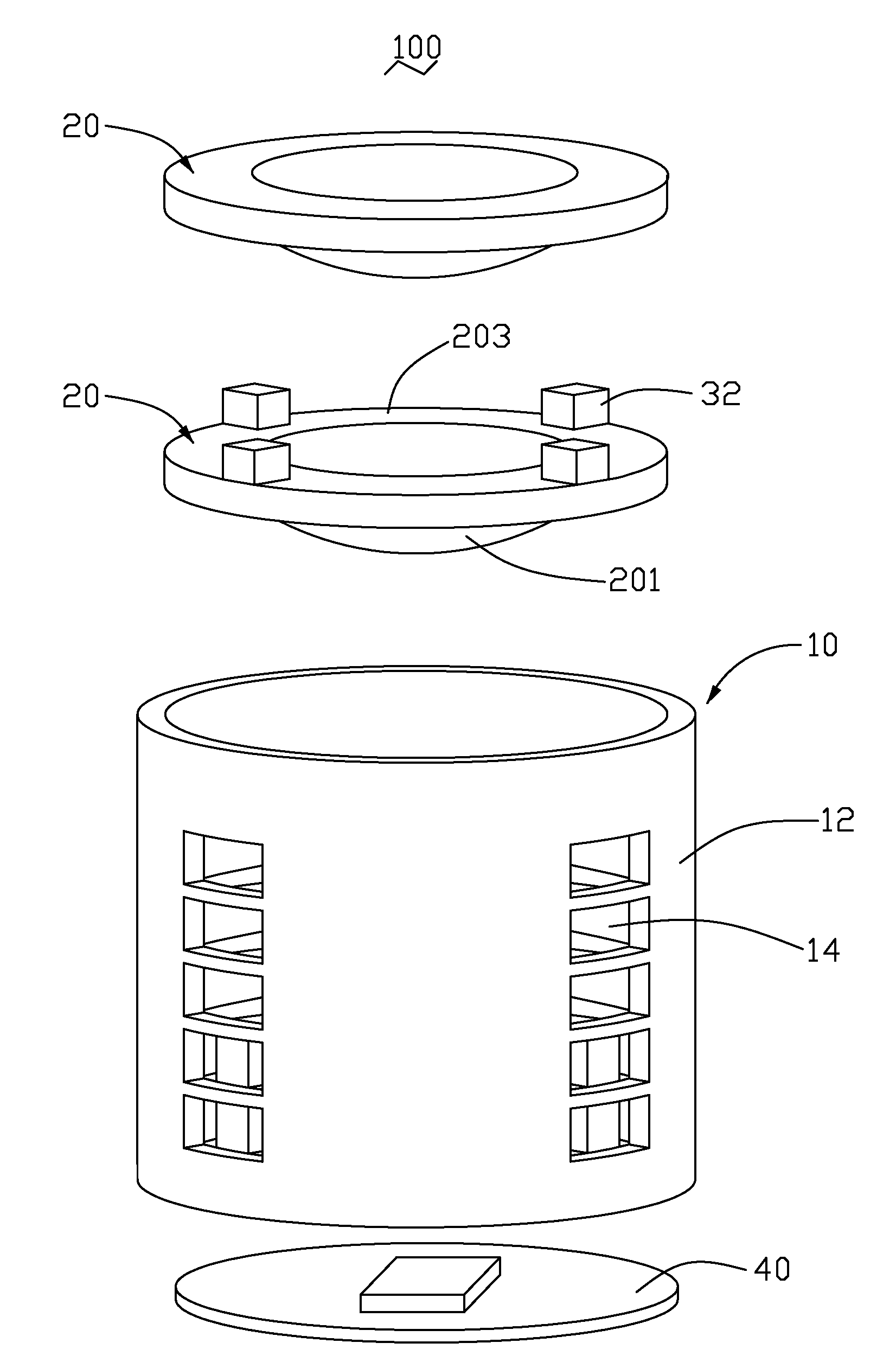
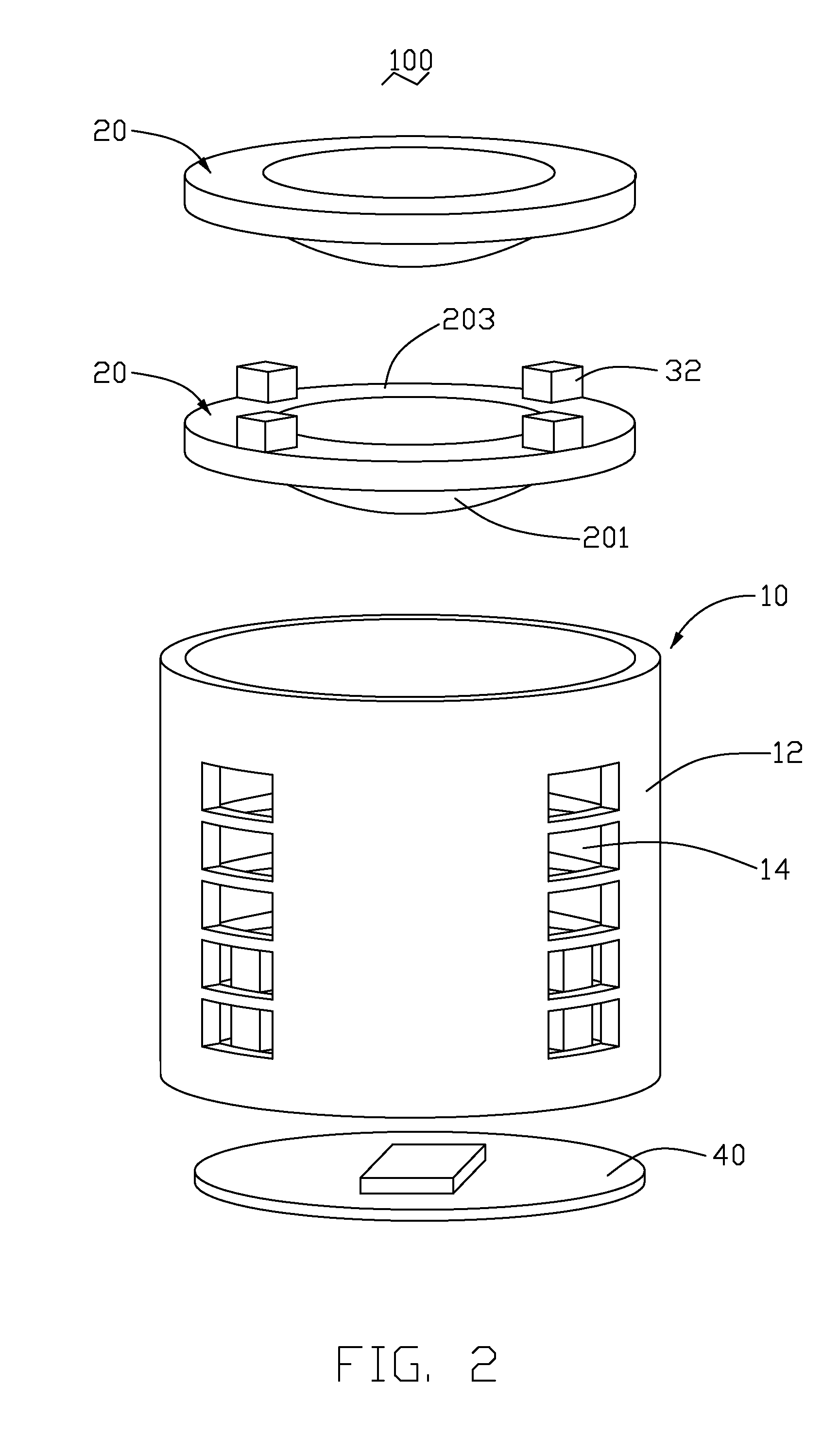
[0017]Referring to FIGS. 1-3, a first embodiment of a camera module 100 includes a lens module (not labeled) and an image sensor 40. The lens module includes a barrel 10, a plurality of lenses 20 and at least one spacer provided between each of the lenses 20 and their neighboring lenses 20. The lenses 20 and the spacer are received in the barrel 10. The image sensor 40 is located on an imaging plane of the lens module.

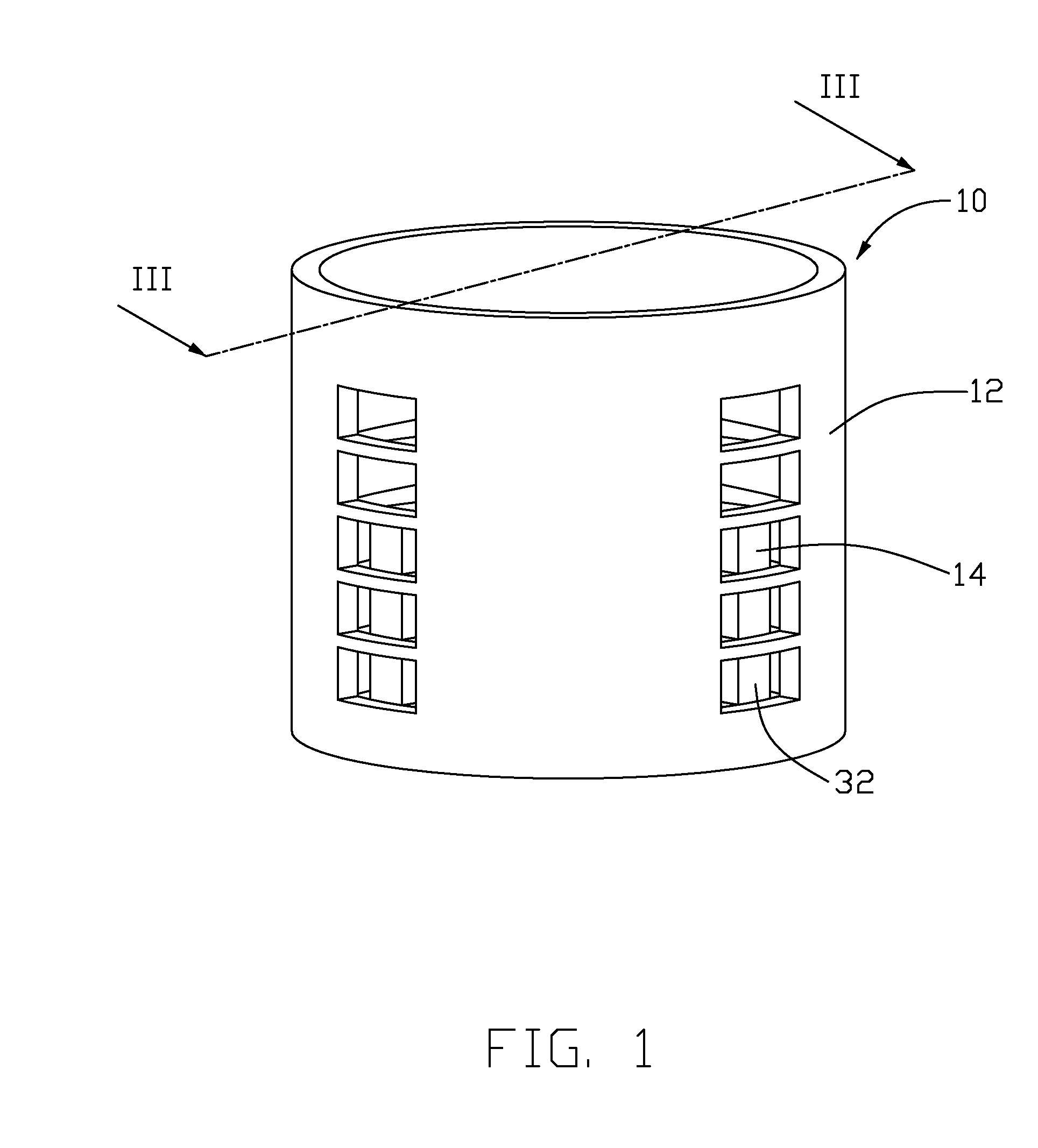
[0018]The barrel 10 is a hollow cylinder including a sidewall 12. Twenty through holes 14 are defined on the sidewall 12 and arranged in four rows along an axis of the barrel 10.

[0019]The lenses 20 are spherical or aspherical lenses used to focus the light onto the image sensor 40. Each of the lenses 20 includes a base 203 and an optical portion 201 in a central area thereof.

[0020]Each of the at least one spacers includes four blocks 32 formed on the base 203 of one of the lenses 20 and four windpipes (not labeled) defined between the four blocks 32. The blocks 32 are ...


PUM


Abstract

A camera module (100) includes a lens module and an image sensor (40), wherein the lens module includes a barrel (10), a plurality of lenses (20) and at least one spacer provided between each pair of neighboring lenses, wherein at least one through hole (14) is defined on a sidewall (12) of the barrel, the spacer is provided with a windpipe communicating with the at least one through hole, and the lenses and the spacer are received in the barrel; the image sensor is located on an imaging plane of the plurality of lenses.

Description

CROSS-REFERENCE TO RELATED APPLICATION [0001]This application is related to a co-pending U.S. patent application (Attorney Docket No. [US11701]), entitled “LENS MODULE AND CAMERA MODULE USING THE SAME”, by Ching-Lung Jao et al. Such application has the same assignee as the present application and is concurrently filed herewith. The disclosure of the above-identified application is incorporated herein by reference.BACKGROUND OF THE INVENTION [0002]1. Field of the Invention[0003]The present invention generally relates to camera modules and especially, to a lens module and a ventilated camera module using the same.[0004]2. Description of Related Art[0005]Nowadays, digital camera modules are in widespread use. Portable electronic devices such as mobile phones and personal digital assistants (PDAs) are becoming increasingly multifunctional, and digital camera modules are now widely available as a special feature for portable electronic devices, consequently the integration of digital cam...

Claims


Application Information

Patent Timeline
IPC IPC(8): G02B7/02
CPCG02B7/021
Inventor CHEN, TIEN-PAO
Owner HON HAI PRECISION IND CO LTD
Why Eureka
Try Eureka