
Bearing end cover

a technology of bearing end and bearing plate, which is applied in the direction of bearing unit rigid support, bearing components, shaft and bearings, etc., can solve the problems of difficult installation, dislocation, limited compatibility,

Inactive Publication Date: 2008-03-20
BALDOR ELECTRIC COMPANY
View PDF15 Cites 6 Cited by
  • Summary
  • Abstract
  • Description
  • Claims
  • Application Information

AI Technical Summary

Problems solved by technology

However, they may be difficult to install, dislodge through incidental contact, or have limited compatibility due to size or shape (i.e., they do not accommodate a range of different bearing housing sizes).

Method used


Image

  • Bearing end cover
  • Bearing end cover
  • Bearing end cover

Examples


Embodiment Construction

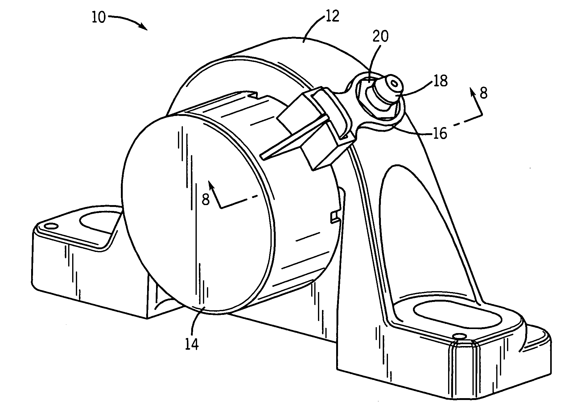
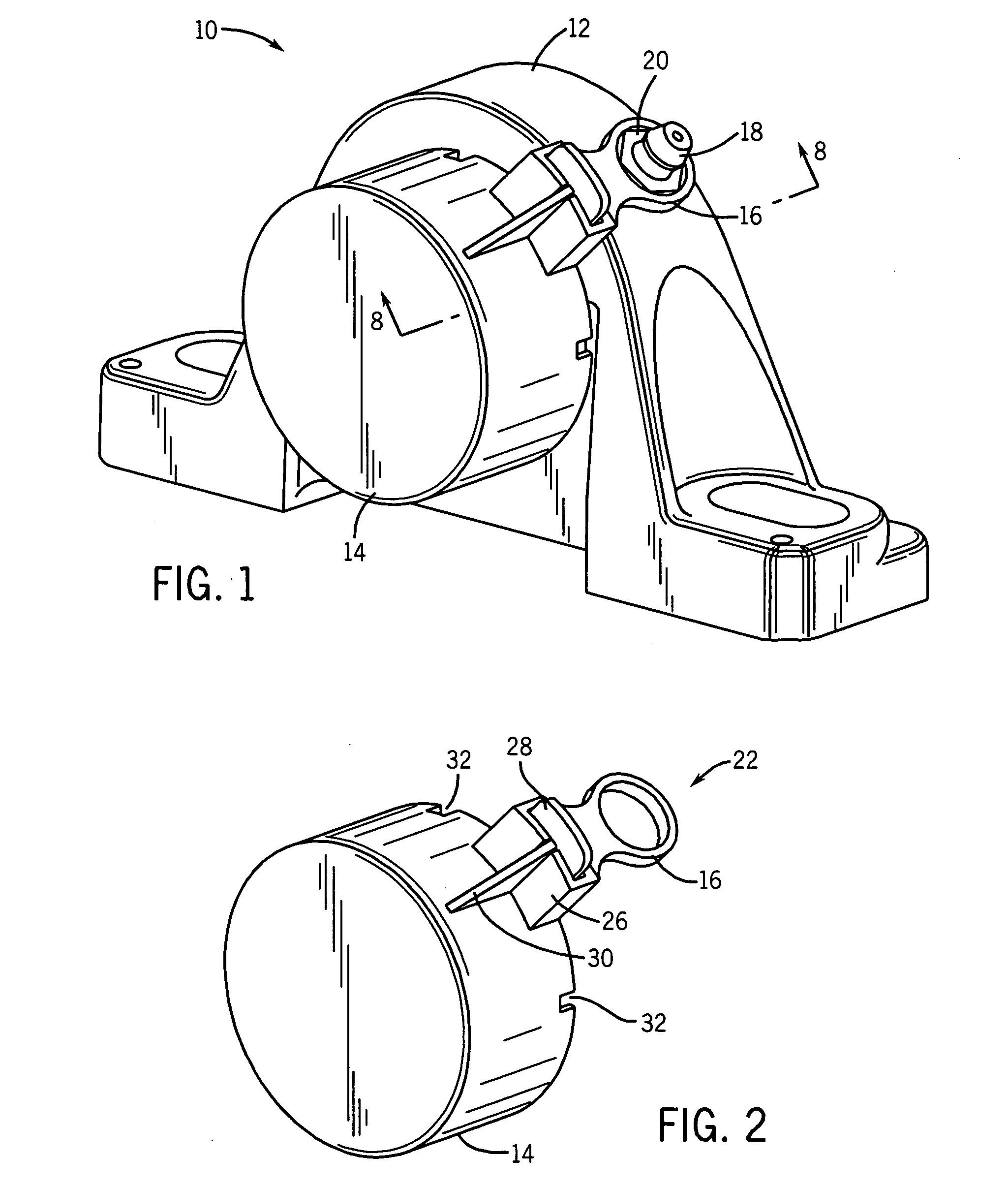
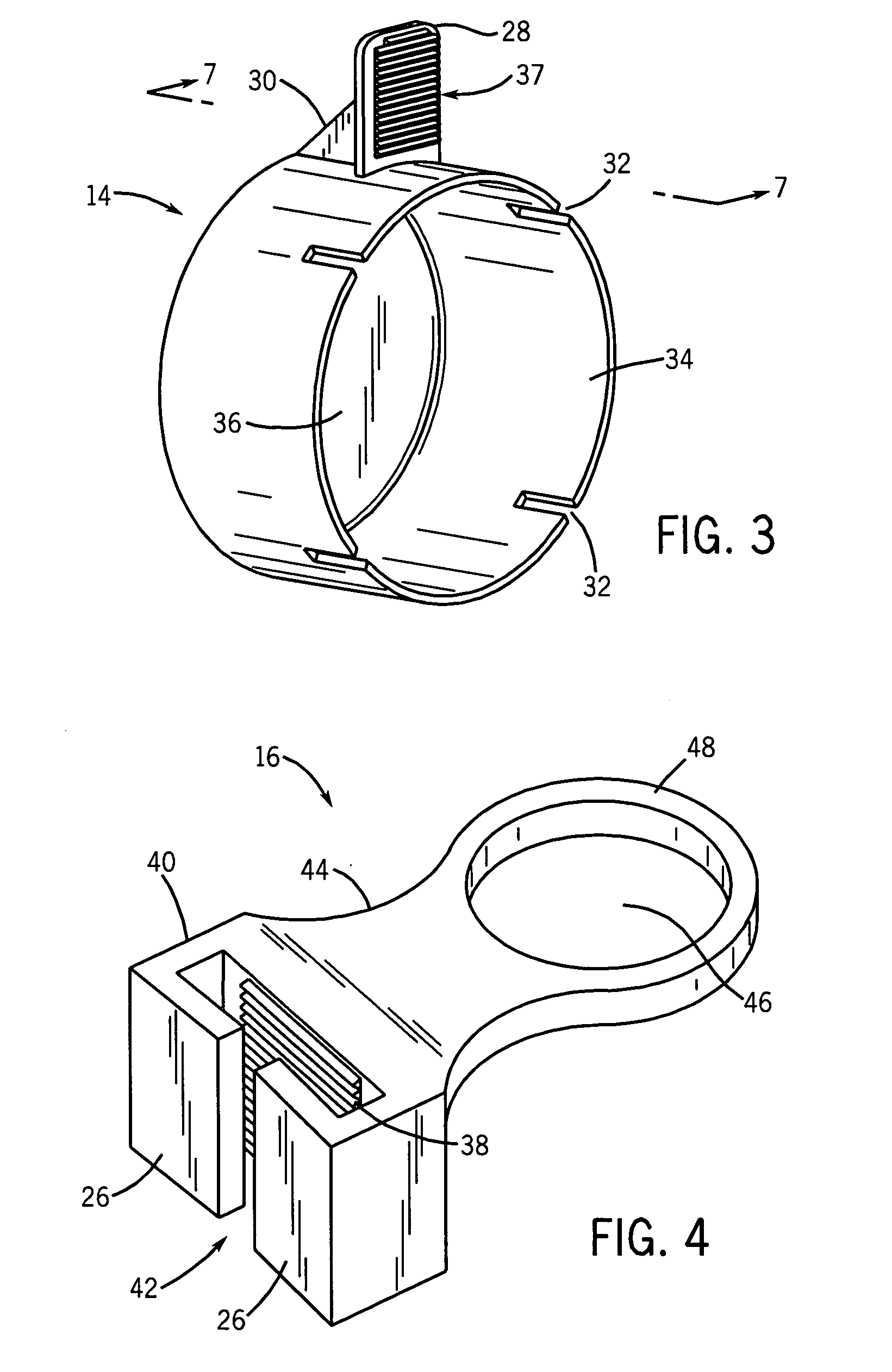
[0017]In accordance with exemplary embodiments disclosed herein, an injection moldable end cover assembly is provided. The arrangement may be adapted to fit a range of bearing housing styles, including standard pillow blocks, tapped base pillow blocks, two-bolt flanges, four-bolt flanges, flange brackets, piloted flanges, wide-slot take-up bearings, and top angle take-up bearings. As will be discussed in greater detail below, the end cover assembly may also fit bearing housings having a variety of sizes and dimensions without external machining of the bearing housing. The end cover assembly functions as a robust guard and cannot be easily dislodged by incidental contact.

[0018]Turning initially to FIG. 1, a housing assembly is illustrated in accordance with an exemplary embodiment of the present invention and is generally referred to by the reference numeral 10. The housing assembly includes a bearing housing 12. The bearing housing 12 may be configured to house a variety of sizes of...


PUM


Abstract

A bearing cover includes a clip securable to a bearing housing and an end cover securable to the clip to cover a central opening of the bearing housing. The clip may be secured to a grease fitting or other structural component attached to the bearing housing. The relative location and engagement of the clip and end cover may be adjusted to accommodate different sizes and configurations of bearing housings.

Description

BACKGROUND[0001]The present invention relates generally to bearings, such as antifriction bearings. More particularly, the invention relates to add-on covers for covering an opening in bearing housings or over shafts supported by bearings.[0002]Bearings are ubiquitous throughout industry. Many different types and styles of bearings have been developed and are in use, such as ball bearings, roller bearings, so forth. Moreover, housing styles for such bearings include pillow block housings, flanged housings, and tapped base housings. The particular type of bearing and housing style are generally selected based upon such factors as the mechanical constraints of the application (i.e., the layout of equipment), and the anticipated loading.[0003]Most industrial bearings include a housing in which a bearing set or insert is supported. The housing, regardless of the style, has a central opening that receives a rotating member to be supported by the bearing. The central aperture generally ex...

Claims


Application Information

Patent Timeline
IPC IPC(8): F16C33/76
CPCF16C33/723F16C35/047F16C33/6622
Inventor DRAKE, MICHAEL D.TIERNO, PHILIP C.DEWACHTER, RYAN N.
Owner BALDOR ELECTRIC COMPANY
Learn More