
Temperature sensing grease fitting with alarm

a technology of temperature sensing and grease fittings, applied in the field of bearings, can solve the problems of bearings being vulnerable to failure, degrading the useful life of bearings, and both of these prior solutions have certain limitations, so as to reduce the downtime of bearings, preventative maintenance of bearings, and determine the condition of bearings

Active Publication Date: 2014-09-18
REGAL BELOIT AMERICA
View PDF7 Cites 3 Cited by
  • Summary
  • Abstract
  • Description
  • Claims
  • Application Information

AI Technical Summary

Benefits of technology

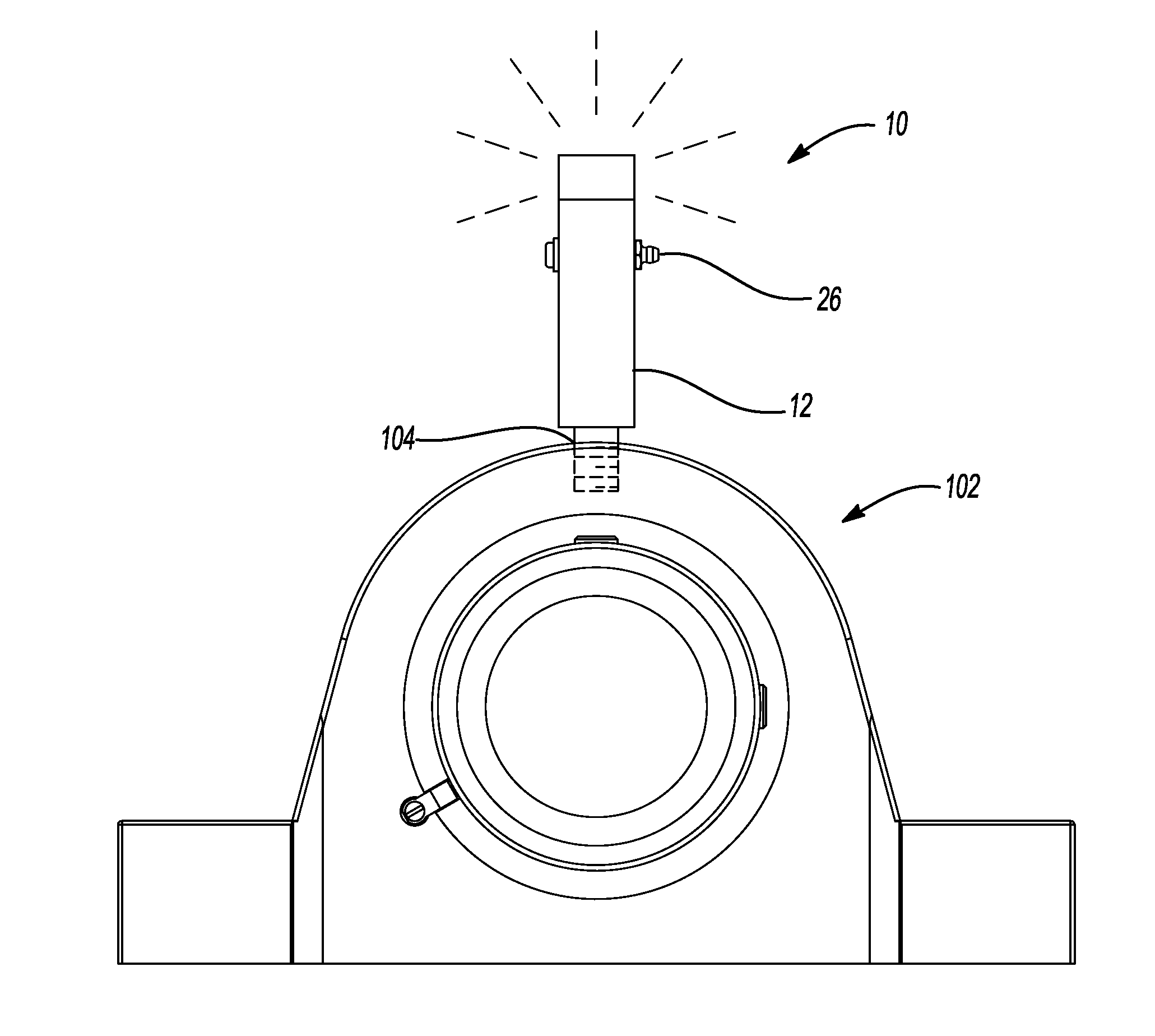
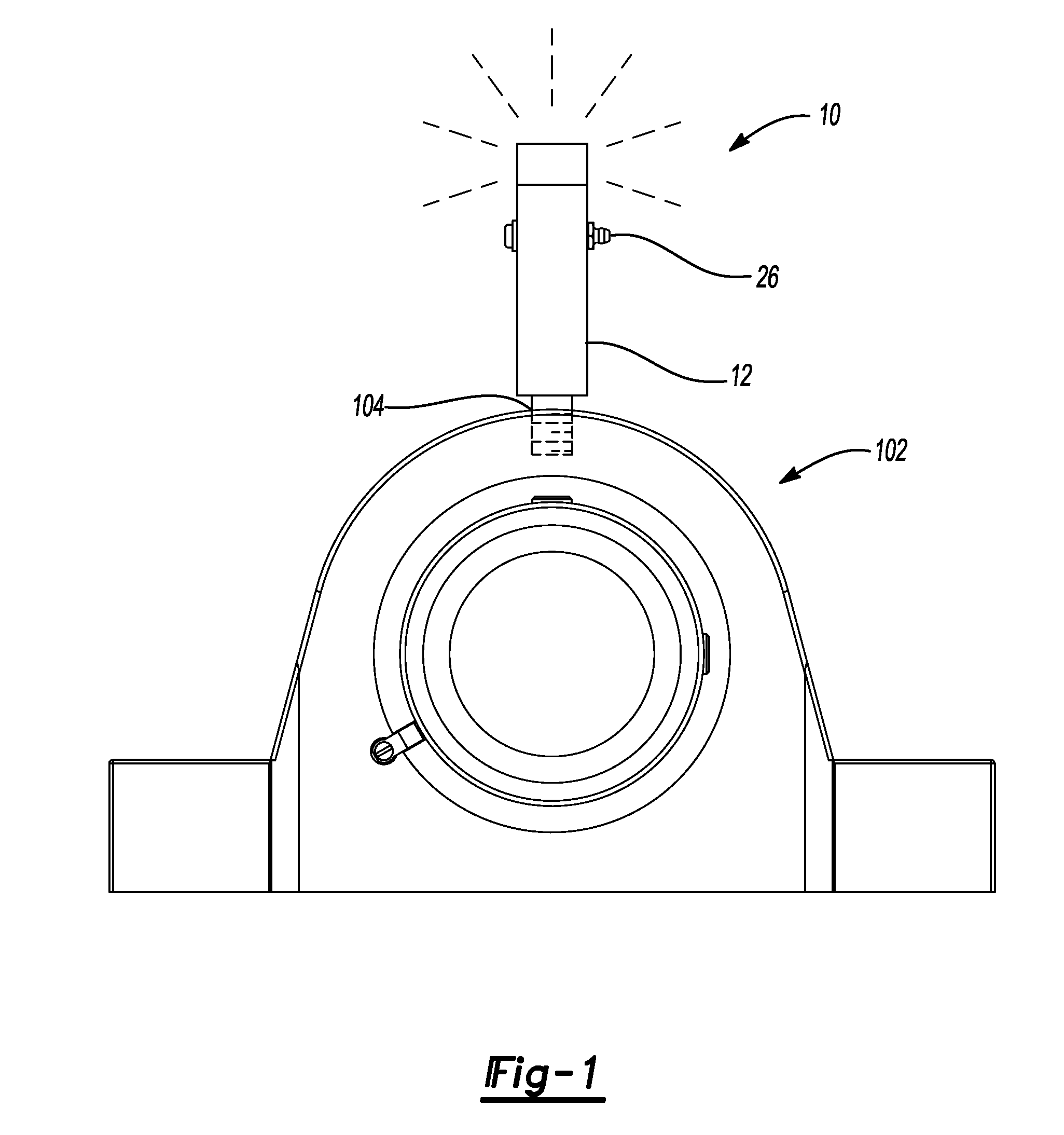
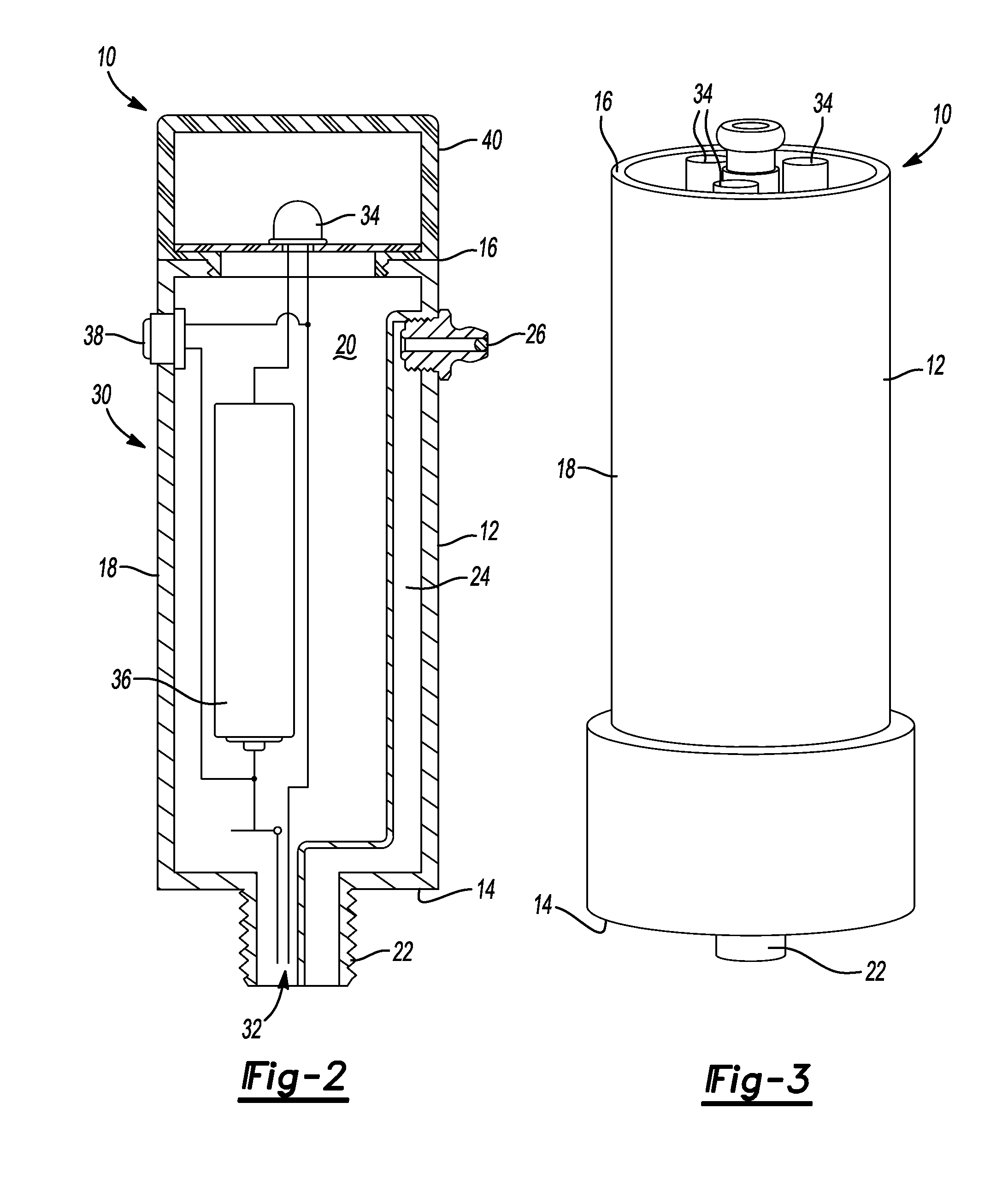
The patent text describes a monitoring system for a bearing that uses a visual indicator to alert if the bearing temperature reaches a certain point. The system includes a battery power supply that can be either an external power supply or a battery housed in the monitoring system. The useful life of the battery is limited, so previous attempts were made to incorporate a timer into the system. The monitoring system can be screwed into the lubrication hole of the bearing housing and will not use any power in the off state. The monitoring system can include multiple temperature sensors and alert devices that help the end user better determine the condition of the bearing and may assist in preventative maintenance and reduce bearing down time. The system also has output capabilities that allow the user to connect the alert device to an external system, if desired.

Problems solved by technology

A rise in temperature can be caused by many factors, but the result is degradation of the bearing useful life.
Both of these prior solutions have certain limitations.
This issue often leaves these bearings vulnerable to failure without maintenance personnel having sufficient warning.
Should a failure like this happen, damage to the bearing and surrounding equipment may occur.
If the power is supplied by the batteries, a life limitation is put on the unit.
The unit can only take measurements for a given period before the batteries run out of power.
Although this does increase the life of the product, the life is still limited by the useful life of the battery power source.

Method used


Image

  • Temperature sensing grease fitting with alarm
  • Temperature sensing grease fitting with alarm
  • Temperature sensing grease fitting with alarm

Examples


Embodiment Construction

[0017]Example embodiments will now be described more fully with reference to the accompanying drawings.

[0018]Example embodiments are provided so that this disclosure will be thorough, and will fully convey the scope to those who are skilled in the art. Numerous specific details are set forth such as examples of specific components, devices, and methods, to provide a thorough understanding of embodiments of the present disclosure. It will be apparent to those skilled in the art that specific details need not be employed, that example embodiments may be embodied in many different forms and that neither should be construed to limit the scope of the disclosure. In some example embodiments, well-known processes, well-known device structures, and well-known technologies are not described in detail.

[0019]The terminology used herein is for the purpose of describing particular example embodiments only and is not intended to be limiting. As used herein, the singular forms “a,”“an,” and “the” ...


PUM


Abstract

A bearing temperature monitoring system for detecting a temperature of bearing grease within a bearing housing. The bearing temperature monitoring system comprises a housing mountable to the bearing housing, a power source selectively outputting an electrical current, and an electrical circuit. The electrical circuit includes a temperature sensor component electrically coupled to the power source. The temperature sensor component can be responsive to a change in temperature such that the temperature sensor component opens or closes the electrical circuit at a predetermined temperature even in the absence of an applied electrical current. The electrical circuit further includes an alert device electrically coupled to the power source and the temperature sensor component that outputs an alert in response to the temperature sensor component.

Description

CROSS-REFERENCE TO RELATED APPLICATIONS[0001]This application claims the benefit of U.S. Provisional Application No. 61 / 777,450, filed on Mar. 12, 2013. The entire disclosure of the above application is incorporated herein by reference.FIELD[0002]The present disclosure relates to bearings and, more particularly, relates to a temperature sensing grease fitting having an alarm or alerting system.BACKGROUND AND SUMMARY[0003]This section provides background information related to the present disclosure which is not necessarily prior art. This section also provides a general summary of the disclosure, and is not a comprehensive disclosure of its full scope or all of its features.[0004]Bearing temperature rise is a good indicator that a bearing is not working at optimum conditions. A rise in temperature can be caused by many factors, but the result is degradation of the bearing useful life.[0005]Previously, bearing temperature measurements were made using a thermocouple. A thermocouple us...

Claims


Application Information

Patent Timeline
Patent Type & Authority Applications(United States)
IPC IPC(8): F16C41/00F16C33/66
CPCF16C33/6603F16C41/00G01K13/02F16C33/6625F16C35/047F16C17/243F16C19/525F16C33/102F16C2233/00G01K5/70G01K13/08
Inventor LEWIS, MATTHEW I.
Owner REGAL BELOIT AMERICA
Learn More