Roller bearing and z-stop for a two-step roller finger follower

a roller bearing and roller finger follower technology, applied in the direction of valve arrangements, machines/engines, mechanical equipment, etc., can solve the problems of reducing the life and durability of the bearing, hla leakage, and affecting the operation of the valve train,

Inactive Publication Date: 2008-03-27
DELPHI TECH INC
View PDF3 Cites 3 Cited by
  • Summary
  • Abstract
  • Description
  • Claims
  • Application Information

AI Technical Summary

Benefits of technology

[0013]Briefly described, a two-step RFF in accordance with the invention includes a high-lift follower portion that rotates relative to a low-lift follower portion about a pivot shaft in the low-lift follower portion. A lost-motion spring is disposed between the high-lift follower and the low-lift follower to bias the high-lift follower away from the low-lift follower. An improved roller shaft bearing arrangement is provided that can be used in the space provided for prior art bearings, permitting the advantageous use of longer bearings, more bearings, and / or a larger diameter roller shaft. A z-stop is provided to limit the range of travel of the high-lift follower away from the low-lift follower. Various z-stop embodiments are provided using a ground path other than directly through the roller shaft, including a sleeve surrounding the roller shaft that grounds the high-lift follower to the low-lift follower independent of the roller shaft.

Problems solved by technology

If the force of the lost motion spring is too small, the high-lift follower may not be able to stay in contact with the high-lift cam lobe under all engine operating conditions causing valve train clatter.
If the spring force is too large, the force of the lost motion spring may overcome the force of an internal spring in the HLA, causing the HLA to leak down and become undesirably compressed and depleted of oil.
Shorter bearings reduce the life and durability of the bearings and can cause excessive wear to the mating components served by the bearings.
Further, a non-hardened housing as required for rolling over the end of the housing cannot be also employed as a satisfactory z-stop for the high-lift follower.

Method used


Image

  • Roller bearing and z-stop for a two-step roller finger follower
  • Roller bearing and z-stop for a two-step roller finger follower
  • Roller bearing and z-stop for a two-step roller finger follower

Examples


first embodiment

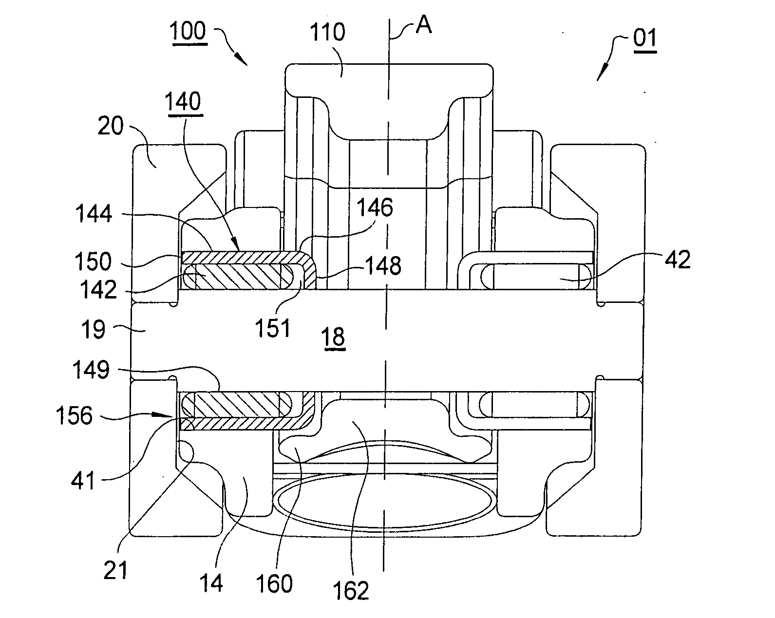
[0034]RFF 100 of a first embodiment provides an improved roller shaft bearing that includes provisions for a mechanical z-stop to prevent leak down by limiting the amount of upward travel of the high-lift follower relative to the low-lift follower, as imposed by the lost motion spring, when the high-lift follower is on the base circle portion of the high-lift cam.

[0035]Referring to FIG. 5, the features shown to the left of split line A depict first embodiment 100 in accordance with the present invention, and the features shown to the right depict the equivalent prior art features 01 generally as shown in FIGS. 1-4 and discussed above. Bearing unit 140 includes cup shaped member 146 formed to include cylindrical portion 144, inside flange 148 and end surface 150. Note that the portion of cup member 146 near end surface 150 is open, that is, lacking in an enclosing flange as in the prior art. Bearing unit 140 also includes a plurality of needle bearings 142 received within cylindrical...

embodiment 200

[0039]Second RFF embodiment 200, shown in FIG. 6, also provides an improved roller shaft bearing that includes provisions for a mechanical z-stop. Two identical bearing units 240 each include cup member 246 formed to include cylindrical portion 244, inside flange 248, end flange 250, and nose portion 252. Each bearing unit 240 also includes a plurality of hardened needle bearings 242, substantially identical with bearings 142 in FIG. 5, received within cylindrical portion 244 of cup member 246. Unlike cup 46 where only a portion was hardened, cup member 246, like cup member 146, may be hardened in its entirety, including nose portion 252, since it is not necessary to roll over an end of cup member 246 to laterally retain needle bearings 242.

second embodiment

[0040]To assemble the second embodiment, each hardened cup member 246 is oriented so that outside flange 250 faces outward relative to the outward opening of shaft orifice 41. Then, a tool (not shown) is used to press against hardened outside flange 250 until the flange contacts an outside wall 253 of low-lift follower 14, pressing the cup member into place in direction 156 so that outside flange 250 will be positioned in close relationship with an inside surface 51 of roller 20. Then, roller shaft 18 is fitted through central opening 249 of each cup member 246 to thereby centrally align shaft 18 relative to cup member 246 to form an annular needle bearing chamber 251. Roller shaft 18 preferably is not in contact with the inner surfaces of nose portions 252. After needle bearings 242 are aligned and positioned within bearing chamber 251, rollers 20 are press-fittedly received by roller shaft ends 19, and optionally secured to shaft ends 19 by, for example, welding, bonding, riveting...


PUM


Abstract

A two-step roller finger follower having a high-lift follower portion that pivots on a pivot shaft disposed on a low-lift follower portion, and having a lost-motion spring disposed between the high-lift follower and the low-lift follower to bias the high-lift follower toward the high lift cam lobe. Various bearing cups and roller shaft sleeve embodiments are shown, all of which allow for improved shaft and needle bearing arrangements. A z-stop formed by the bearing cups and / or the shaft sleeve limits the range of travel of the high-lift follower with respect to the low-lift follower. Various z-stop embodiments are provided including a non-contacting roller shaft sleeve that grounds the high-lift follower to the low-lift follower independent of the roller shaft.

Description

RELATIONSHIP TO OTHER APPLICATIONS AND PATENTS[0001]This application claims the benefit of U.S. Provisional Application No. 60 / 847,245, filed Sep. 26, 2006.TECHNICAL FIELD[0002]The present invention relates to roller finger followers for actuating the valves of internal combustion engines; more particularly, to two-step roller finger followers for controllably changing the lift of engine valves; and most particularly, to a two-step roller finger follower having a bearing cup and / or roller shaft. A travel stop for preventing leak-down of the hydraulic lash adjuster is also provided.BACKGROUND OF THE INVENTION[0003]Two-step roller finger followers (RFF) for the controllable lift of compression valves in a valve train of an internal combustion engines are well known. An RFF extends between a hydraulic lash adjuster (HLA) and the stem of a valve. Engagement with an eccentric cam lobe of an engine camshaft causes the RFF to be pivoted about the HLA and thereby to depress the valve stem, ...

Claims


Application Information

Patent Timeline
Patent Type & Authority Applications(United States)
IPC IPC(8): F01L1/34
CPCF01L1/185F01L2105/02F01L2103/00F01L13/0036F01L2001/186F01L2303/00F01L2305/02
Inventor TAWAF, CYNTHIA ALIPINSKI, ANDREW J.BAUMAN, WILLIAM D.KANGAS, CARL R.STONE, ALBERT C.WILUSZ, ERIC G.FERNANDEZ, HERMESHENDRIKSMA, NICK J.
Owner DELPHI TECH INC
Why Eureka
Try Eureka