Belt conveyor and method

a belt conveyor and belt technology, applied in the direction of conveyors, conveyor parts, transportation and packaging, etc., can solve the problem of rendering the entire belt conveyor unusable while maintenance is performed, and achieve the effect of facilitating the use of an over-center pivot and low modulus

Active Publication Date: 2008-03-27
DEMATIC
View PDF22 Cites 42 Cited by
  • Summary
  • Abstract
  • Description
  • Claims
  • Application Information

AI Technical Summary

Benefits of technology

[0009]According to further aspects, the continuous belt may comprise a low modulus characteristic of the type disclosed in commonly assigned U.S. Pat. No. 6,811,018, which is hereby incorporated herein by reference. The use of a low modulus characteristic continuous belt as a conveying surface facilitates the use of an over-center pivot arm by allowing approximately 0.75% or more stretch to the continuous belt during movement of the pivot arms from a slack or maintenance position to the operating position. The drive roller may be lagged to create a high-friction interface between the drive roller and the continuous belt. Th

Problems solved by technology

However, typical belt conveyors require extensive disassembly to perform maintenance tasks such as replacing a belt, replac

Method used


Image

  • Belt conveyor and method
  • Belt conveyor and method
  • Belt conveyor and method

Examples


Embodiment Construction

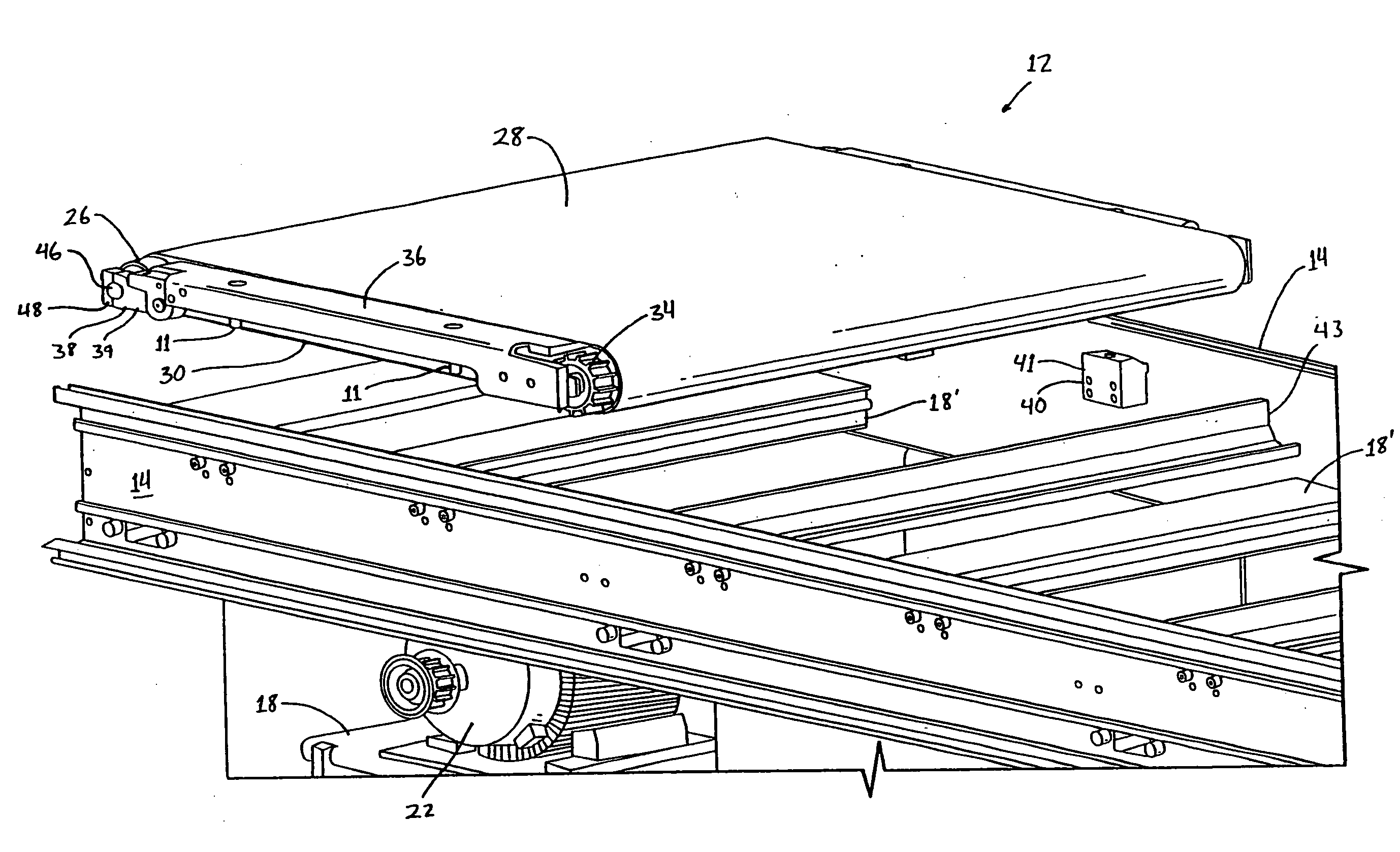
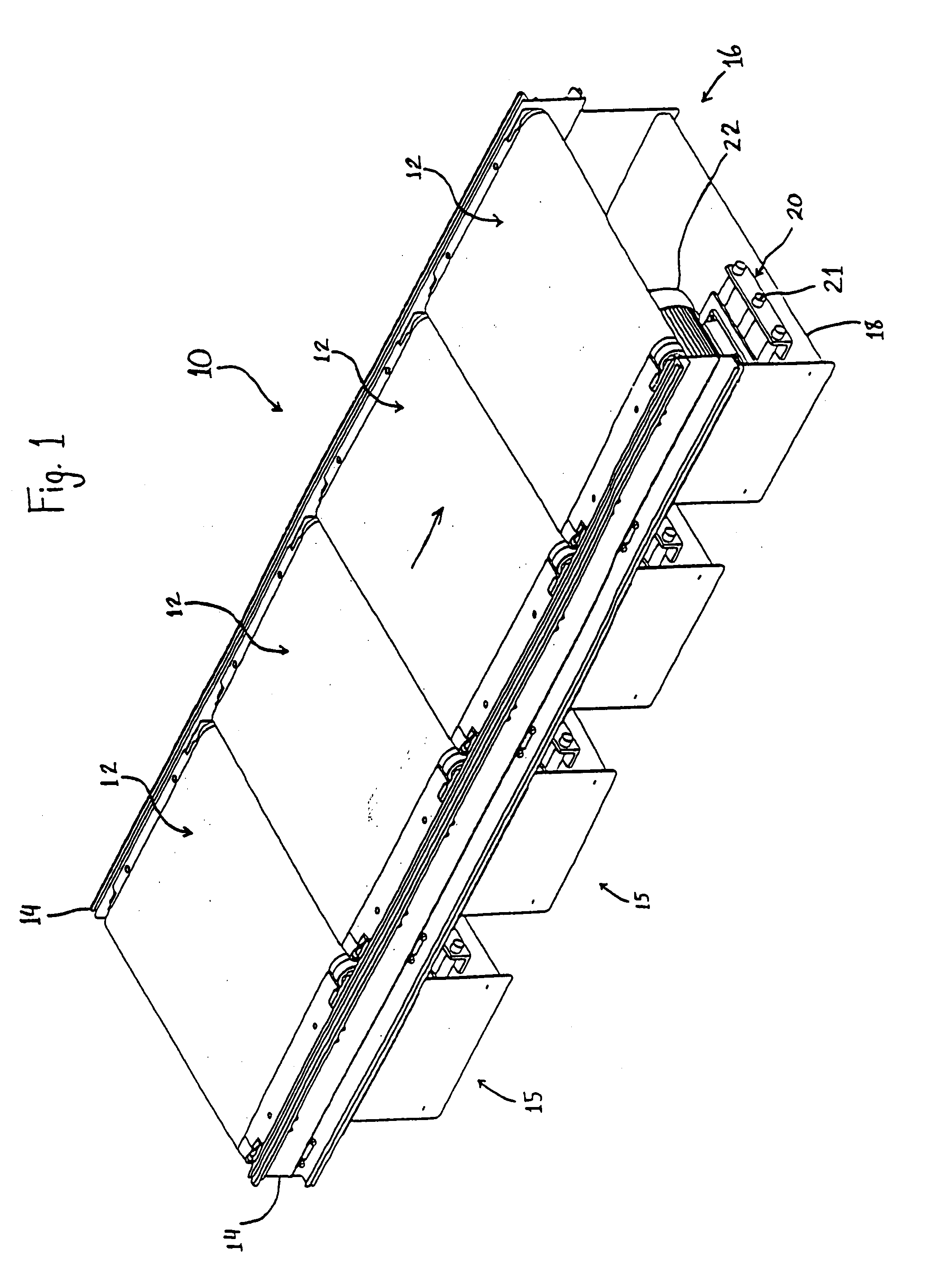
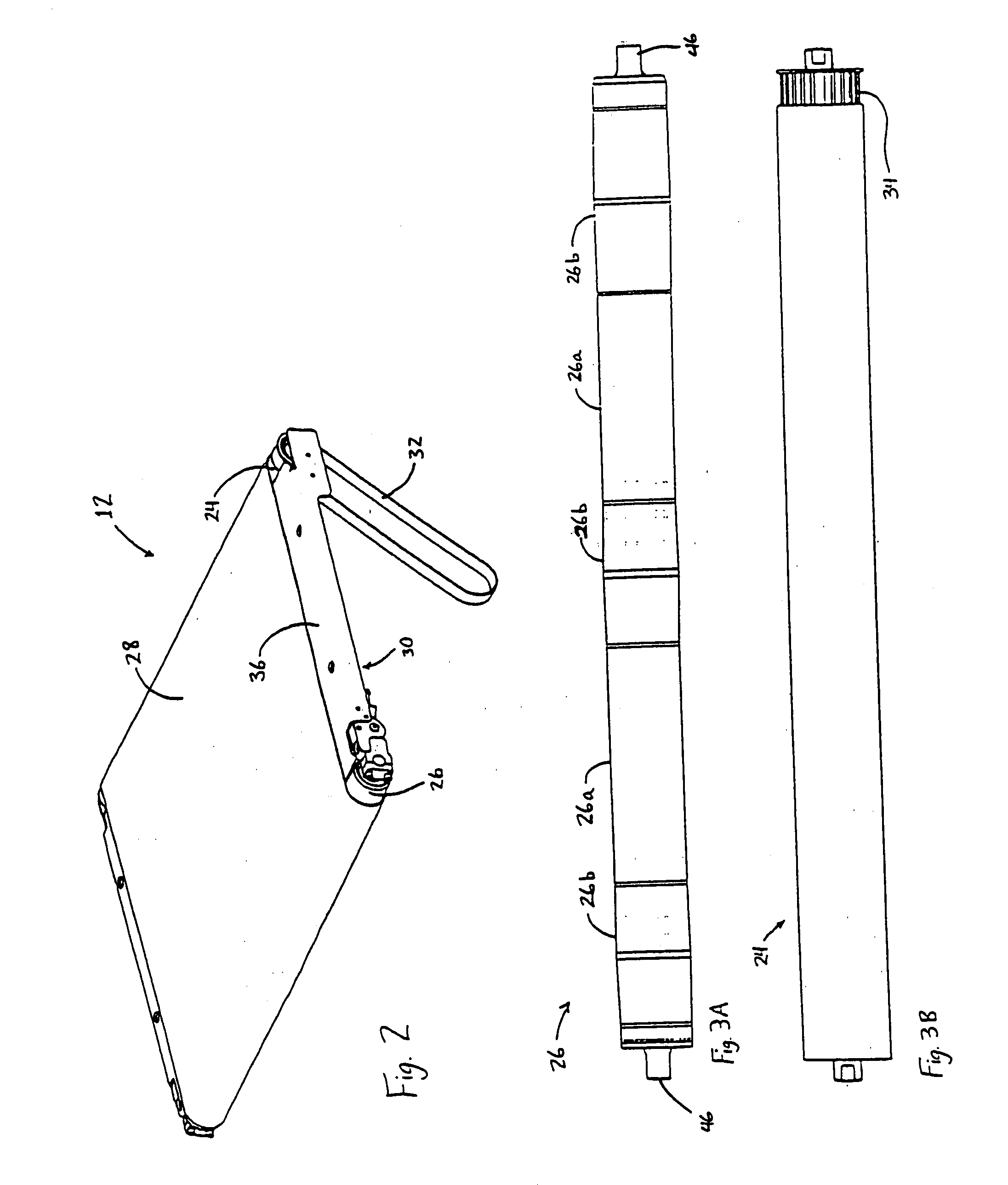
[0026]Referring now to the drawings and the illustrative embodiments depicted therein, a belt conveyor 10 includes a frame assembly 16 supporting at least one zone assembly 15 (FIGS. 1 and 4). Frame assembly 16 may include opposite sidewalls or side frames 14 and cross members 18, 18′ (FIGS. 1, 4, and 7), and may be supported from the floor or a platform, such as by frame legs (not shown), or by other structures such as wall-mount brackets, or chains, cables, or rods suspended from a ceiling (not shown). Zone assembly 15 includes a removable belt module 12, a portion of sidewalls 14, a rotary power transmission device 32, a motor 22, and an adjustment mechanism 20. Removable belt module 12 is positioned between sidewalls 14, and is operable to convey articles in a direction of conveyance illustrated by the arrow (FIG. 1). In one embodiment, each removable belt module 12 includes a powered roller or drive pulley 24 and at least one other roller or pulley 26, such as an idler pulley (...


PUM


Abstract

A belt conveyor includes at least one belt module defined by at least one drive pulley and at least one other pulley that is generally an idler pulley positioned between opposite sidewalls of the conveyor, and having a continuous belt routed around the drive pulley and the other pulley. The drive pulley is operable to drive the continuous belt around the pulleys to move articles along the zone assembly. The belt conveyor may incorporate features that allow for improved maintenance methods and reduced down time during service intervals. These features may include a removable belt module, at least one pulley mounted on at least one pivot arm, or a combination thereof. The belt may have a low modulus characteristic and may be initially stretched when the belt is reeved or routed around the pulleys and the pivot arms are moved into their operating position.

Description

CROSS REFERENCE TO RELATED APPLICATION[0001]The present invention claims the benefit of U.S. provisional application Ser. No. 60 / 826,788, filed Sep. 25, 2006, which is hereby incorporated herein by reference in its entirety.FIELD OF THE INVENTION[0002]The present invention relates generally to material handling conveyors and, more particularly, to belt conveyors.BACKGROUND OF THE INVENTION[0003]It is known to provide zones of belts along a belt conveyor, where each zone consists of a zone assembly that includes a powered roller and at least one additional roller, such as and idler or freely rotating roller, having a continuous belt reeved around the rollers. However, typical belt conveyors require extensive disassembly to perform maintenance tasks such as replacing a belt, replacing a roller, lubricating bearings, or the like, rendering the entire belt conveyor unusable while maintenance is performed.SUMMARY OF THE INVENTION[0004]The present invention provides a belt conveyor, remov...

Claims


Application Information

Patent Timeline
IPC IPC(8): B65G21/10
CPCB65G21/06B65G15/00
Inventor BRAYMAN, MATTHEW T.KARAS, JOHN M.COTTER, DAVID H.
Owner DEMATIC
Why Eureka
Try Eureka