Microactuated suspension with shear transmission of force

a technology of microactuation and suspension, which is applied in the direction of magnetic recording, data recording, instruments, etc., can solve the problems of conventionally required reduction of metal thickness in the area, design limitation of energy required to do this, etc., and achieve the effect of reducing the size of the suspension, reducing the cost of manufacture, and improving the effect of microactuation

Inactive Publication Date: 2007-11-06
MAGNECOMP
View PDF1 Cites 53 Cited by
  • Summary
  • Abstract
  • Description
  • Claims
  • Application Information

AI Technical Summary

Benefits of technology

[0008]With reduced size of suspensions and new materials, such as laminates, being used, e.g. as flexible circuits and as circuit supports, that do not lend themselves to conventional microactuation approaches, the invention adapts these new materials and combines them with microactuators to take advantage of their unique properties to better effect microactuation at lower cost of manufacture, and to minimize design compromises in the suspension parts.
[0009]It is an object, therefore, to provide a disk drive suspension using a laminate of first and second outer layers and an inner layer comprised of plastic such as polyimide. It is a further object to provide microactuation using as a typical laminate one comprised of a first outer layer of a metal such stainless steel about 0.0012 inch thick, although this can be varied for particular purposes, an inner layer of extensible material, such as a plastic like about 0.008 inch polyimide, and a second outer layer of metal such as stainless steel about 0.002 inch thick. The thickness of the inner and second out layers can also be varied as required for different effects. It is a further object to form a suspension member of a three layer laminate, using one outer layer as or connected to the proximate portion of the suspension, the other outer layer as or connected to the suspension distal portion, coupling, e.g. gluing microactuators to the two outer layers, and effecting relative movement between the outer layers by elongating or contracting the plastic inner layer, to cause micromovement between the first and second outer layers and thus the proximate and distal portions of the suspension and the slider carried by the distal portion. It is a further object to provide a new microadjustment system for microactuated suspensions. The relatively thick middle layer, combined with its low modulus of elasticity, means that the microactuating PZTs (piezoelectric crystals) can drive the motion in shear mode instead of bending mode.

Problems solved by technology

The energy required to do this is a design limitation.
The conventionally required reduction in metal thickness in the area of bending is a further design problem.

Method used


Image

  • Microactuated suspension with shear transmission of force
  • Microactuated suspension with shear transmission of force
  • Microactuated suspension with shear transmission of force

Examples


Embodiment Construction

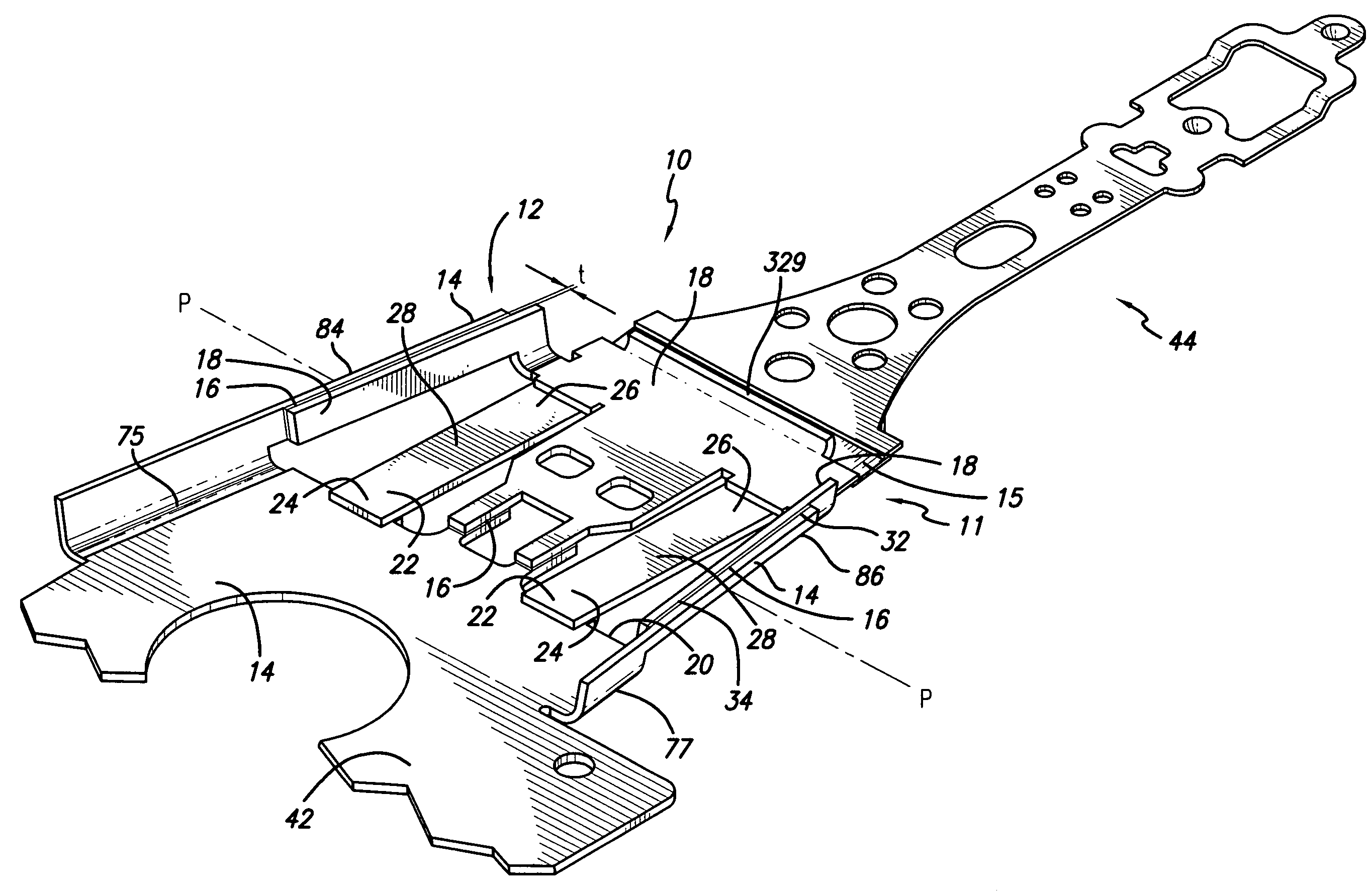
[0030]Modulus is the relationship of applied stress (force per area) to strain (movement per length). Low modulus means that small amounts of force on the outer layers are necessary to displace (stretch, shrink) the inner material. Shear mode means that the left and right sides of the suspension elongate or contract as required by distorting the inner plastic material in shear.

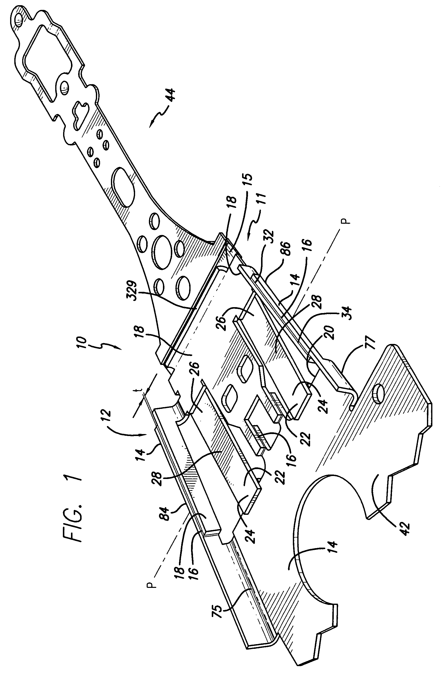
[0031]With reference now to the drawings in detail, in FIG. 1 microactuated disk drive suspension 10 comprises a laminate 12 of a first outer layer 14, a middle plastic layer 16, and a second outer layer 18. Plastic layer 16 extends in a plane P. A dimensionally variable microactuator 22, attached to laminate 12 has first and second end regions 24, 26, respectively, and a middle region 28 extending through the plastic layer plane P. First and second outer layers 14, 18 mount the microactuator 22, comprising one or two microactuators, as shown, by first and second end regions 24, 26 respectively, so that dimens...


PUM

PropertyMeasurementUnit
thickaaaaaaaaaa
thickaaaaaaaaaa
thickaaaaaaaaaa

Abstract

A disk drive suspension has a base portion, a spring portion, and a beam portion carrying a slider at a disk. The base portion is a laminate of two inextensible outer layers and an inner layer that is extensible in shear. Microactuators that expand or contract are attached by their opposite ends in angled or parallel relation to the respective outer layers to shift the outer layers relative to each other as a function of shearing in the inner layer to shift the slider at the disk.

Description

RELATED APPLICATION[0001]This application is a continuation in part of application Ser. No. 10 / 210,409 filed Jul. 31, 2002, now U.S. Pat. No. 6,894,876, which application claims the benefit of U.S. Provisional Application Ser. No. 60 / 309,825, filed Aug. 1, 2001.STATEMENT REGARDING FEDERALLY SPONSORED RESEARCH OR DEVELOPMENT[0002]Not ApplicableREFERENCE TO A MICROFICHE APPENDIX[0003]Not ApplicableBACKGROUND OF THE INVENTION[0004]1. Field of the Invention[0005]This invention relates to disk drive suspensions, and more particularly to such suspensions having microactuated movement of the slider over a disk. In the invention the microactuator first and second, or proximal and distal, ends are attached respectively first and second outer layers of a laminate bonded to an inner layer that moves in shear to accommodate the relative movement of the outer layers. The outer layers are attached to or are part of the suspension base portion which in turn is connected to the suspension beam port...

Claims


Application Information

Patent Timeline
Patent Type & Authority Patents(United States)
IPC IPC(8): G11B21/24G11B5/48G11B5/55
CPCG11B5/4826G11B5/5552G11B5/4833
Inventor COON, WARREN
Owner MAGNECOMP
Why Eureka
Try Eureka