Device For Reducing Microorganisms With Ultrasonic Waves

a technology of ultrasonic waves and microorganisms, which is applied in the direction of water treatment multi-stage treatment, mechanical vibration separation, separation process, etc., can solve the problems of difficult to completely sterilize the liquid, inability to irradiate the entire liquid to be processed, and cost disadvantage, so as to prevent the adhesion of suspended particles and reduce the frequency of maintaining the device

a technology of ultrasonic waves and microorganisms, which is applied in the direction of water treatment multi-stage treatment, mechanical vibration separation, separation process, etc., can solve the problems of difficult to completely sterilize the liquid, inability to irradiate the entire liquid to be processed, and cost disadvantage, so as to prevent the adhesion of suspended particles and reduce the frequency of maintaining the device

US20080073260A1Inactive Publication Date: 2008-03-27ELEKON SCI

Image

  • Device For Reducing Microorganisms With Ultrasonic Waves
  • Device For Reducing Microorganisms With Ultrasonic Waves
  • Device For Reducing Microorganisms With Ultrasonic Waves

Examples


Embodiment Construction

[0018]Preferred embodiments of the present invention will be described below based on the drawings.

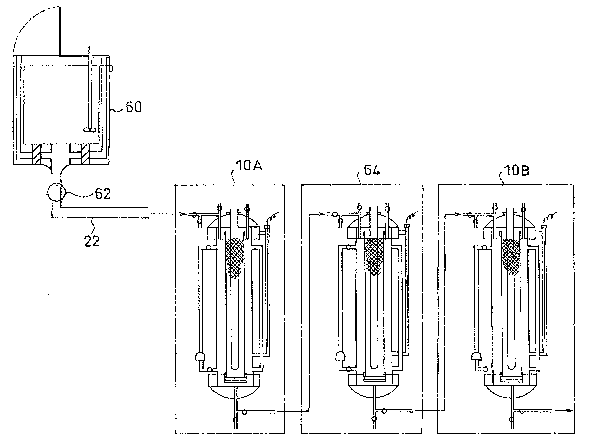
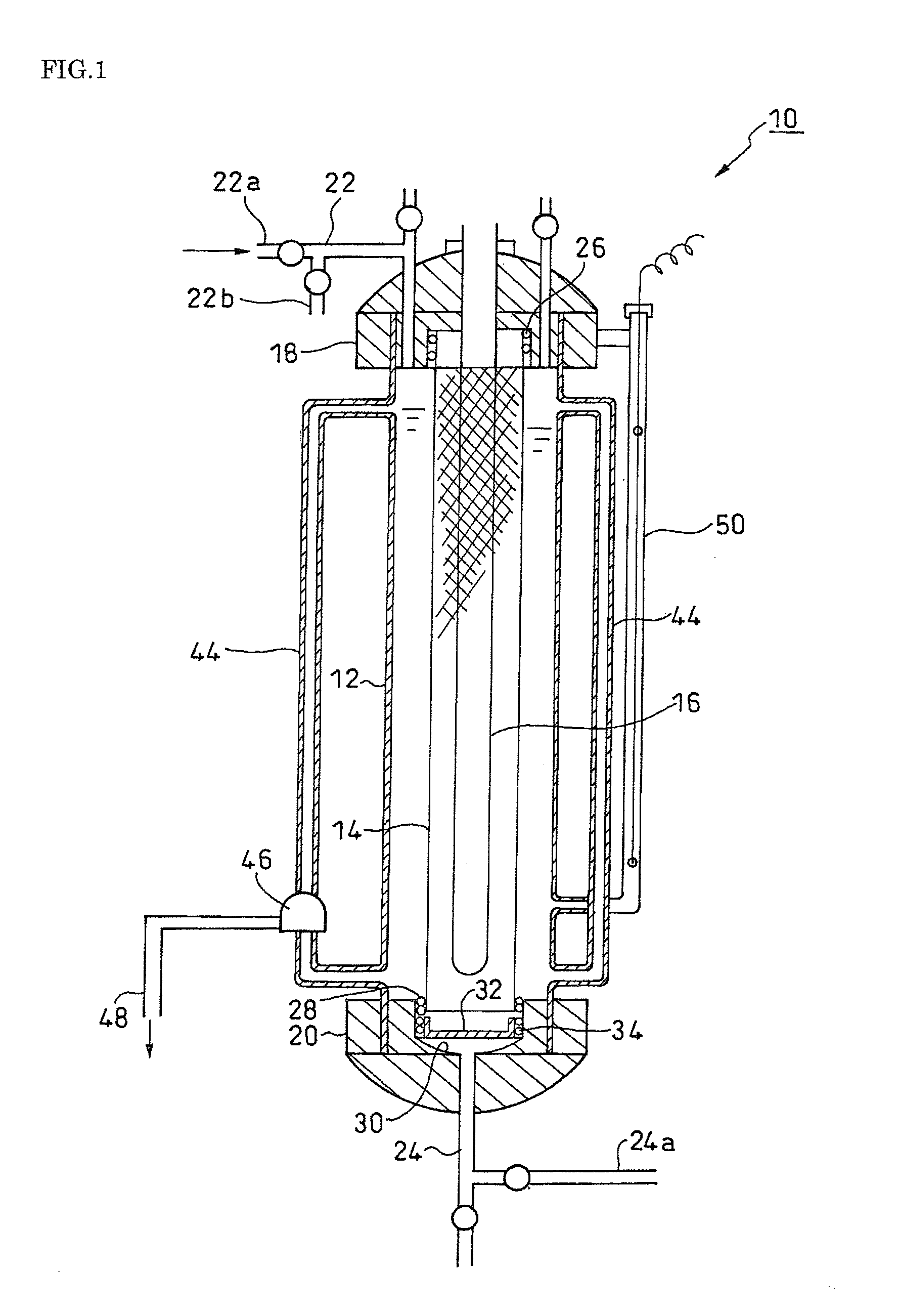
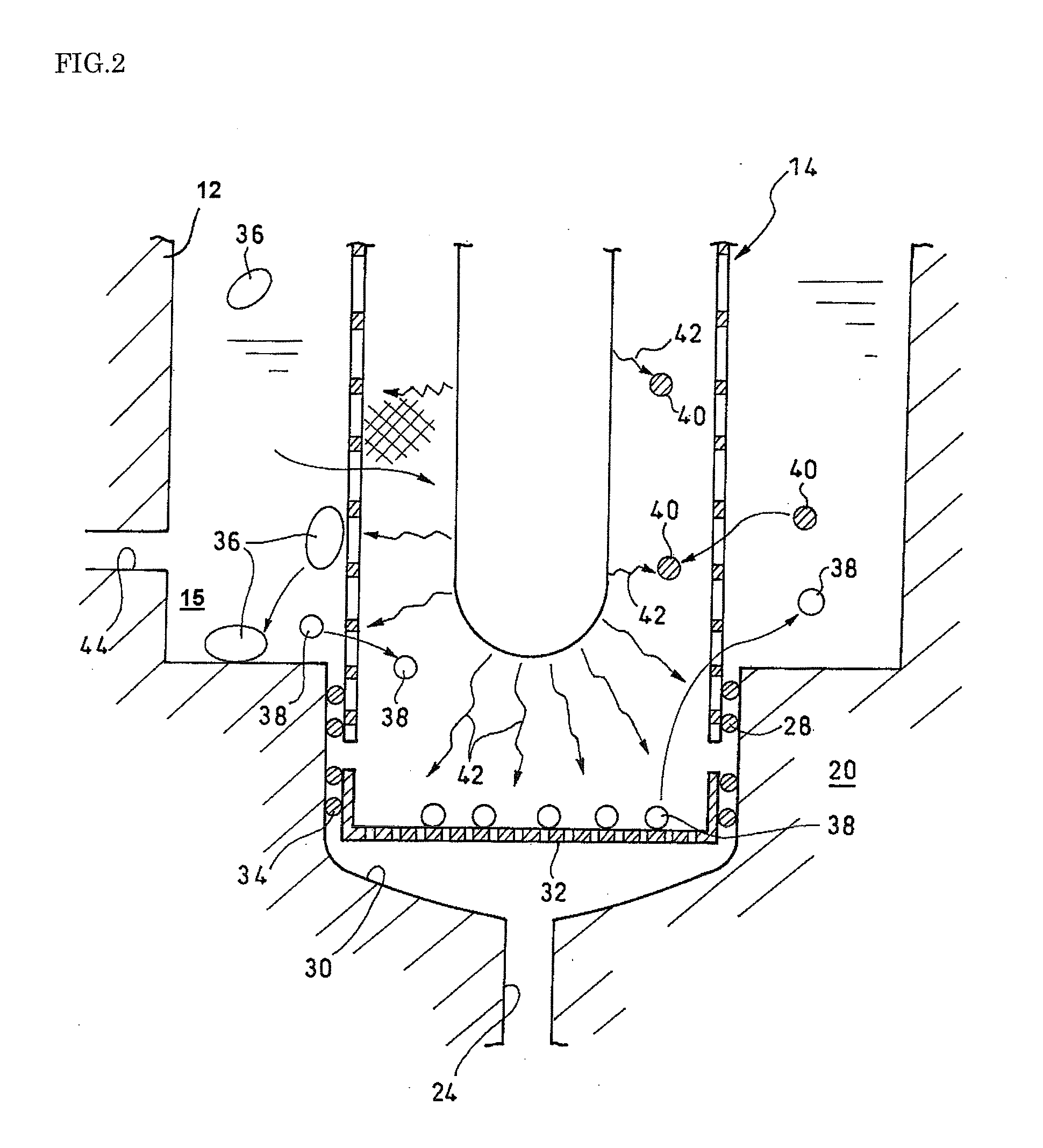
[0019]FIG. 1 shows a sectional view of a device for reducing microorganisms 10 according to an embodiment of the present invention. In this view, the device for reducing microorganisms 10 includes an outer cylinder 12 which liquid to be processed flows into, a mesh inner cylinder 14 which is disposed inside the outer cylinder 12, and an ultrasonic oscillator 16 which is disposed inside the mesh inner cylinder 14.

[0020]The outer cylinder 12 is made of resin or corrosion resistant metal. An upper cap 18 is fit in watertightly at the top of the outer cylinder 12 and a lower cap 20 is fit in watertightly at the bottom of the outer cylinder 12. The upper cap 18 is provided with an inlet tube for liquid to be processed 22 and the lower cap 20 is provided with an outlet tube for processed liquid 24.

[0021]The mesh inner cylinder 14 is made of hard material which resists attenuating ultrasonic ...


PUM

PropertyMeasurementUnit
pore diameteraaaaaaaaaa

Abstract

A device for reducing microorganisms comprising:an outer cylinder which liquid to be processed flows into;a mesh inner cylinder which is disposed inside the outer cylinder; andan ultrasonic oscillator which is disposed inside the mesh inner cylinder.

Description

RELATED APPLICATIONS[0001]This application claims priority to the Japanese Patent Application 2006-260439 dated on Sep. 26, 2006 and is hereby incorporated with reference for all purposes.BACKGROUND OF THE INVENTION[0002]1. Field of the Invention[0003]This invention relates to a device for reducing microorganisms with ultrasonic waves, and more particularly, to an improved mechanism for reducing microorganisms in a liquid medium.[0004]2. Prior Art[0005]Among the sterilizers or devices for reducing microorganisms, such as a water-purifying device, whose processing object or medium is liquid, devices making use of photocatalytic action, ultrasonic waves, or filters or the combination thereof have been known. For example, a sterilizer making use of photocatalytic action is disclosed in Japanese Unexamined Patent Application Publication No. 2004-148285 and a device for reducing microorganisms making use of ultrasonic waves is disclosed in Japanese Unexamined Patent Application Publicati...

Claims


Application Information

Patent Timeline
27 Mar 2008
Publication
US20080073260A1
IPC
B01D29/56; B01J19/08; B06B1/20
CPC
C02F1/36; C02F2201/003; C02F2303/16; C02F2303/04; C02F2301/08
Inventors
IDO, KOKICHI