Methods and apparatuses for directing an ion beam source

a technology of ion beam source and ion beam tube, which is applied in the direction of ion beam tube, vacuum evaporation coating, instruments, etc., can solve the problem of reducing the etching effectiveness of the affected sid

Inactive Publication Date: 2008-03-27
CARDINAL CG +1
View PDF26 Cites 41 Cited by
  • Summary
  • Abstract
  • Description
  • Claims
  • Application Information

AI Technical Summary

Problems solved by technology

However, when a conventional anode layer ion beam source is oriented at the preferred angle of incidence, the throw distance around the racetrack...

Method used


Image

  • Methods and apparatuses for directing an ion beam source
  • Methods and apparatuses for directing an ion beam source
  • Methods and apparatuses for directing an ion beam source

Examples


Embodiment Construction

[0032]The following discussion is presented to enable a person skilled in the art to make and use the invention. Various modifications to the illustrated embodiments will be readily apparent to those skilled in the art given the present disclosure as a guide, and the generic principles herein may be applied to other embodiments and applications without departing from the spirit and scope of the present invention as defined by the appended claims. Thus, the present invention is not intended to be limited to the embodiments shown, but is to be accorded the widest scope consistent with the principles and features disclosed herein. The following detailed description is to be read with reference to the figures, in which like elements in different figures have like reference numerals. The figures, which are not necessarily to scale, depict selected embodiments and are not intended to limit the scope of the invention. Skilled artisans will recognize that the examples provided herein have m...


PUM

PropertyMeasurementUnit
Lengthaaaaaaaaaa
Lengthaaaaaaaaaa
Lengthaaaaaaaaaa

Abstract

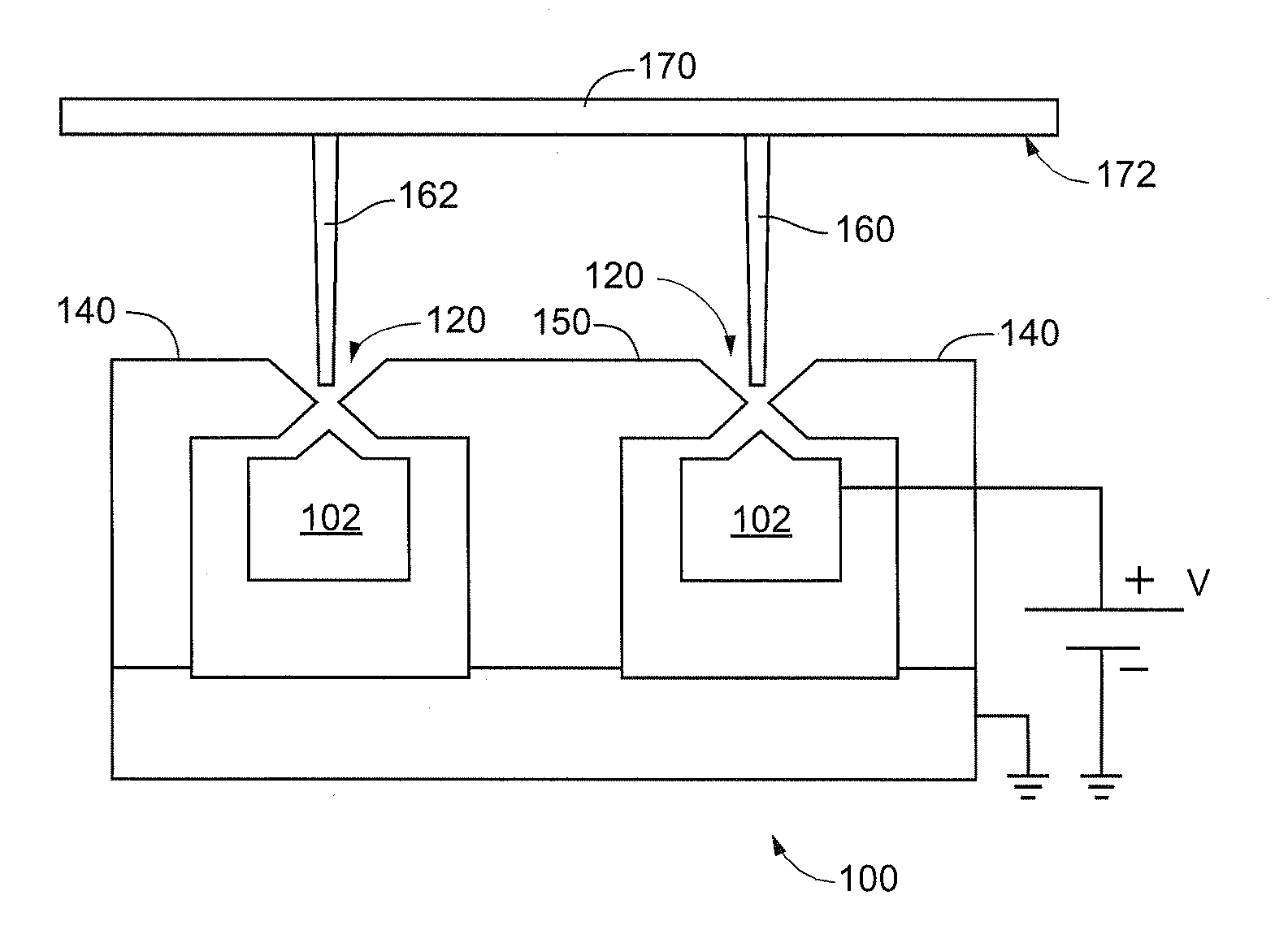
A method and apparatus for directing an ion beam toward a surface of a substrate is disclosed. Certain embodiments of the invention relate generally to ion beam sources adapted to direct ion beams toward a surface of a substrate at an oblique angle of incidence relative to the surface. Certain embodiments of the invention are adapted to direct two ion beam portions toward a substrate surface, the ion beam portions having substantially equal throw distances. Preferred embodiments of the invention may be useful in etching applications, where the angle of incidence and throw distance of two ion beam portions are well suited for etching the surface of a substrate.

Description

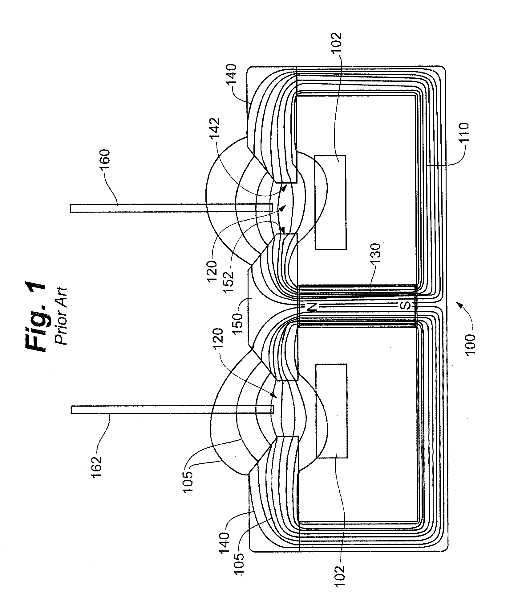
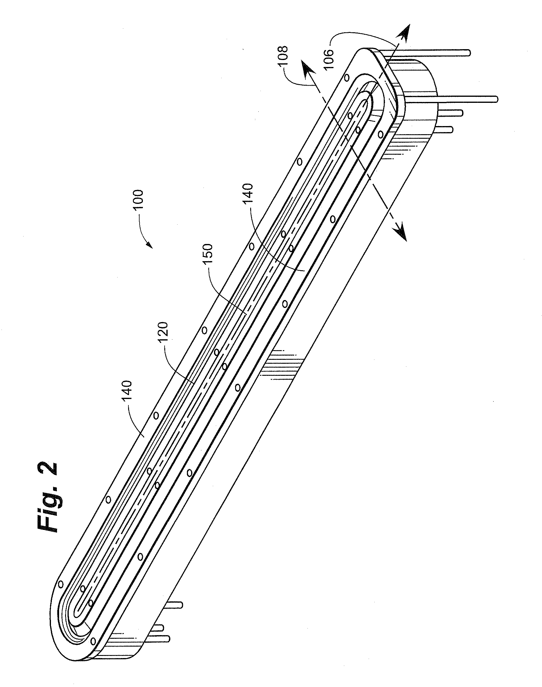
FIELD OF THE INVENTION[0001]The present invention relates generally to ion beam sources, and more particularly to closed-loop ion beam sources.BACKGROUND[0002]An ion beam source is a device that causes gas molecules to be ionized, then focuses, accelerates and / or emits the ionized gas molecules and / or atoms in a beam toward a substrate. Such an ion beam may be used for various purposes including, but not limited to, cleaning a substrate, etching a substrate, milling off a portion of a substrate, and / or depositing film on a substrate.[0003]An ion beam source may, for example, include cathode portions that define an ion-emitting slit. An anode may be arranged adjacent to the slit and the cathode so as to be spaced somewhat from the slit. An electric field may be generated between the anode and the cathode portions, for example, by the application of a voltage source. A magnetic field may be established such that the cathode portions and the ion-emitting slit are part of a magneto-cond...

Claims


Application Information

Patent Timeline
IPC IPC(8): H01J27/00
CPCC23C14/221C23C14/225C23C14/562C23C14/564H01J2237/3151H01J37/08H01J2237/061H01J2237/083H01J27/143
Inventor GERMAN, JOHNHARTIG, KLAUSMADOCKS, JOHN E.
Owner CARDINAL CG
Why Eureka
Try Eureka