Motor seal

a technology of motor seals and seals, which is applied in the direction of sealing/packing, machines/engines, and wellbore/well accessories, etc., can solve the problems of reducing the life of the pumping assembly

Inactive Publication Date: 2008-04-03
WEATHERFORDLAMB
View PDF63 Cites 31 Cited by
  • Summary
  • Abstract
  • Description
  • Claims
  • Application Information

AI Technical Summary

Benefits of technology

[0011]The embodiments described herein relate to an apparatus for sealing and protecting a motor for use in a wellbore. The apparatus includes a housing, a thrust runner and a radial bearing. The thrust runner is configured configured to fit inside the substantially cylindrical housing. The radial bearing is located between the thrust runner and the housing. A flow path is created past the thrust runner by one or more grooves between the housing and the thrust runner, wherein the one or more grooves allow a fluid to flow past the radial bearing.

Problems solved by technology

Often, pressure within the wellbore is insufficient to cause the production fluid to naturally rise through the production tubing to the surface of the wellbore.
During operation, the lubricating fluid absorbs energy from the thrust block and bearing portions, which causes the lubricating fluid to heat up and lose its ability to lubricate over the life of the pumping assembly.
The turbulence creates uneven load patterns on the bearing portion and thrust block.
The uneven load patterns results in enhanced wear and vibration of the bearing portion and the thrust blocks.

Method used


Image

  • Motor seal
  • Motor seal
  • Motor seal

Examples


Embodiment Construction

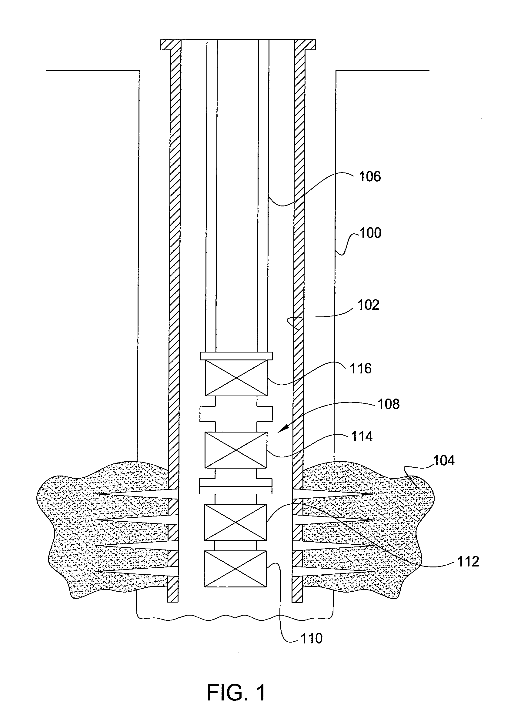
[0022]FIG. 1 is a schematic view of a wellbore 100 according to one embodiment described herein. The wellbore 100 includes a tubular 102 which is secured in the wellbore 100 using cement, not shown. The wellbore 100 and the tubular 102 intersects at least one production zone 104. The tubular 102 is typically a string of casing and / or liner; however, it could be any tubular used in downhole operations. Further, the wellbore 100 may be an open hole wellbore. As shown, a conveyance 106 is within the tubular 102 and coupled to an artificial lift assembly 108. As shown, the conveyance is production tubing; however, it should be appreciated that the conveyance could be any conveyance for delivering the artificial lift assembly 108 into the wellbore 100 for example: a wire line, a slick line, a coiled tubing, a co-rod, a drill string, a casing, etc. The artificial lift assembly 108 pushes the production fluids from the wellbore to the surface of the wellbore 100.

[0023]The artificial lift a...


PUM


Abstract

A method and apparatus for stabilizing a thrust chamber and circulating fluids within a motor seal is described herein. The apparatus includes a thrust chamber having a thrust runner and a radial bearing. A flow path exists through the radial bearing which stabilizes the thrust runner and circulates fluids in the thrust chamber. The flow path may consist of a plurality of grooves located adjacent to the radial bearing.

Description

BACKGROUND OF THE INVENTION[0001]1. Field of the Invention[0002]Embodiments described herein generally relate to a thrust chamber for use in a wellbore. More particularly, embodiments described herein relate to a thrust chamber having a flow path configured to circulate lubricating fluids in a motor seal and stabilize a thrust runner.[0003]2. Description of the Related Art[0004]To obtain hydrocarbon fluids from an earth formation, a wellbore is drilled into the earth to intersect an area of interest within a formation. The wellbore may then be “completed” by inserting casing within the wellbore and setting the casing therein using cement. In the alternative, the wellbore may remain uncased (an “open hole wellbore”), or may become only partially cased. Regardless of the form of the wellbore, production tubing is typically run into the wellbore primarily to convey production fluid (e.g., hydrocarbon fluid, which may also include water) from the area of interest within the wellbore to ...

Claims


Application Information

Patent Timeline
Patent Type & Authority Applications(United States)
IPC IPC(8): E21B4/04
CPCE21B4/003H02K5/132E21B43/128F04D13/10
Inventor HALL, KEVIN
Owner WEATHERFORDLAMB
Why Eureka
Try Eureka