
Power system for carrier rocket upper stage and orbit transfer vehicle

An orbital transfer and launch vehicle technology, applied in the field of power systems, can solve the problems of health and safety threats to R&D and manufacturing personnel, heavy rocket carrying burden, high propellant toxicity, etc., to improve combustion stability, improve serviceability, and reduce supporting facilities. The effect of the device

Inactive Publication Date: 2019-04-16
XIAN AEROSPACE PROPULSION INST
View PDF7 Cites 18 Cited by
  • Summary
  • Abstract
  • Description
  • Claims
  • Application Information

AI Technical Summary

Problems solved by technology

[0004] Because the energy released by liquid fuel is large, the thrust produced is also large, it is easier to control, and the combustion time is longer, therefore, most of the engines of launch vehicles use liquid fuel; the above two engines usually use liquid dinitrogen tetroxide (oxidant) and Unsymmetrical dimethylhydrazine (burning agent) is used as a propellant, which can be stored at room temperature and spontaneously ignites after the two come into contact. However, this type of propellant has high toxicity, high price, and low performance, especially nitrogen The combustion product of methylhydrazine has serious damage to the human body and serious pollution to the environment
[0005] Although the new generation of non-toxic and non-polluting liquid oxygen and kerosene engines developed by China has been used as the main engine on the CZ-5, CZ-6, and CZ-7 launch vehicles, the vehicles still mainly use conventional attitude control engines as rockets. To provide attitude control force, an independent storage tank and supply system are still required (the supply system often adopts a squeeze-type supply system suitable for small thrust engines), which makes the rocket carrying load still heavy, complex in structure, and the propellant is toxic. There is a potential threat to the health and safety of R&D and manufacturing personnel

Method used


Image

  • Power system for carrier rocket upper stage and orbit transfer vehicle
  • Power system for carrier rocket upper stage and orbit transfer vehicle
  • Power system for carrier rocket upper stage and orbit transfer vehicle

Examples


Embodiment Construction

[0025] Below in conjunction with accompanying drawing and specific embodiment content of the present invention is described in further detail:

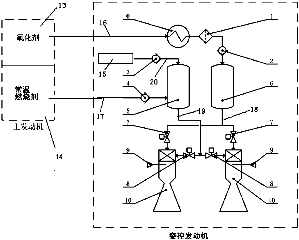
[0026] Such as figure 1 As shown, a power system for the upper stage of a launch vehicle and an orbit transfer vehicle includes a main engine and an attitude control engine.

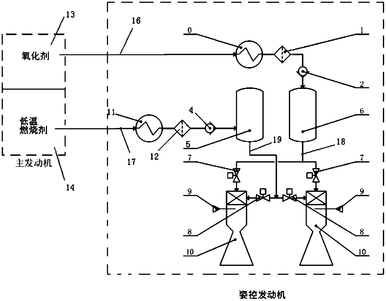
[0027] The main engine is a single low main engine, including the main engine control system, propellant supply system (not shown in the figure) and propellant storage tank; the propellant supply system includes oxidant pump and combustion agent pump; Oxidant storage tank 13 and low pressure normal temperature combustion agent storage tank 5. The attitude-controlled engine includes an attitude-controlled engine control system, a booster device 15 , an oxidant storage tank 6 , a combustion agent storage tank 5 and a thrust chamber 10 . Under the action of the propellant supply system, the propellant storage tank can simultaneously deliver propellant to the thru...


PUM


Abstract

The invention discloses a power system for a carrier rocket upper stage and an orbit transfer vehicle. The power system for the carrier rocket upper stage and the orbit transfer vehicle solves the existing problems that a main engine and an attitude control engine are relatively independent, the carrying burden is relatively heavy,a propellant used in the attitude control engine is rather toxic,and the environment and safety of a human body are seriously threatened. The power system for the carrier rocket upper stage and the orbit transfer vehicle comprises the main engine and the attitude control engine; a propellant tank of the main engine can simultaneously deliver a propellant to a thrust chamber of the main engine and a thrust chamber of the attitude control engine under the action ofa propellant supply system of the propellant tank, and liquid oxygen is used as an oxidant of the propellant; kerosene, or liquid hydrogen or liquid methane is used as an incendiary agent; the detoxication of the attitude control engine is achieved, and integration of the homologous propellant of the main engine and the attitude control engine is achieved; a propellant tank of the attitude control engine can be supplemented after operation through the main engine; and the propellant dosage carried by the attitude control engine during flight can be reduced, thus the weight of the overall system is lowered, and the payload of a carrier is greatly increased.

Description

technical field [0001] The invention belongs to the technical field of aerospace power, and in particular relates to a power system used for the upper stage of a carrier rocket and an orbit transfer aircraft. Background technique [0002] During the flight of the upper stage of the launch vehicle or the orbiter, in addition to the main engine as the main power, the attitude control of the rocket or aircraft must be realized through an independent attitude control engine (referred to as the attitude control engine). This method requires independent propulsion. The propellant storage tank and propellant supply system have complex structures and large masses, which make the carrying burden heavy. [0003] The main engine is generally composed of a thrust chamber, a propellant supply system, and an engine control system. The attitude control engine is generally composed of a booster device, a propellant tank, a propellant supply system, an engine control system and several sets...

Claims


Application Information

Patent Timeline
IPC IPC(8): F02K9/42F02K9/44
CPCF02K9/42F02K9/44
Inventor 武晓欣高玉闪李春红王海燕龚南妮杨永红张航
Owner XIAN AEROSPACE PROPULSION INST
Learn More