Coated fastener

Inactive Publication Date: 2008-04-03
SNOW GERALD F +2
View PDF50 Cites 8 Cited by
  • Summary
  • Abstract
  • Description
  • Claims
  • Application Information

AI Technical Summary

Benefits of technology

[0014]One advantage of the present invention is that an apparatus and method is provided for coating non-ferrous fasteners at a high rate of speed. Another advantage of the present invention is that the apparatus and method coats non-ferrous (such as stainless steel) fasteners and odd shaped fasteners not conveyed on existing equipment. Yet another advantage of the present invention is that the apparatus and method allows the use of standard vibratory feeding systems for fasteners that normally hang vertically by the heads and positions them into a dual durometer belt. Still another advantage of the present invention is that the apparatus and method can be adjusted horizontally for varying size diameter of the fasteners. A further advantage of the apparatus and method allows for processing speeds to greatly surpass current processing speeds, for example, in excess of 30,000 fasteners per hour compared to current processing speeds of 2,500 fasteners per hour. Yet a further advantage of the present invention is that the apparatus and method allows a coating material to be applied to a recess of a fastener in automated equipment.

Problems solved by technology

Although the above-described apparatus has worked well, it does not work for non-ferrous fasteners.
Also, the apparatus does not work for odd shaped fasteners.
Further, the apparatus has a relatively low processing speed such as 2,500 fasteners per hour.
Additionally, the apparatus does not work for depositing coating material into a recess of a fastener.

Method used


Image

  • Coated fastener
  • Coated fastener
  • Coated fastener

Examples


Embodiment Construction

)

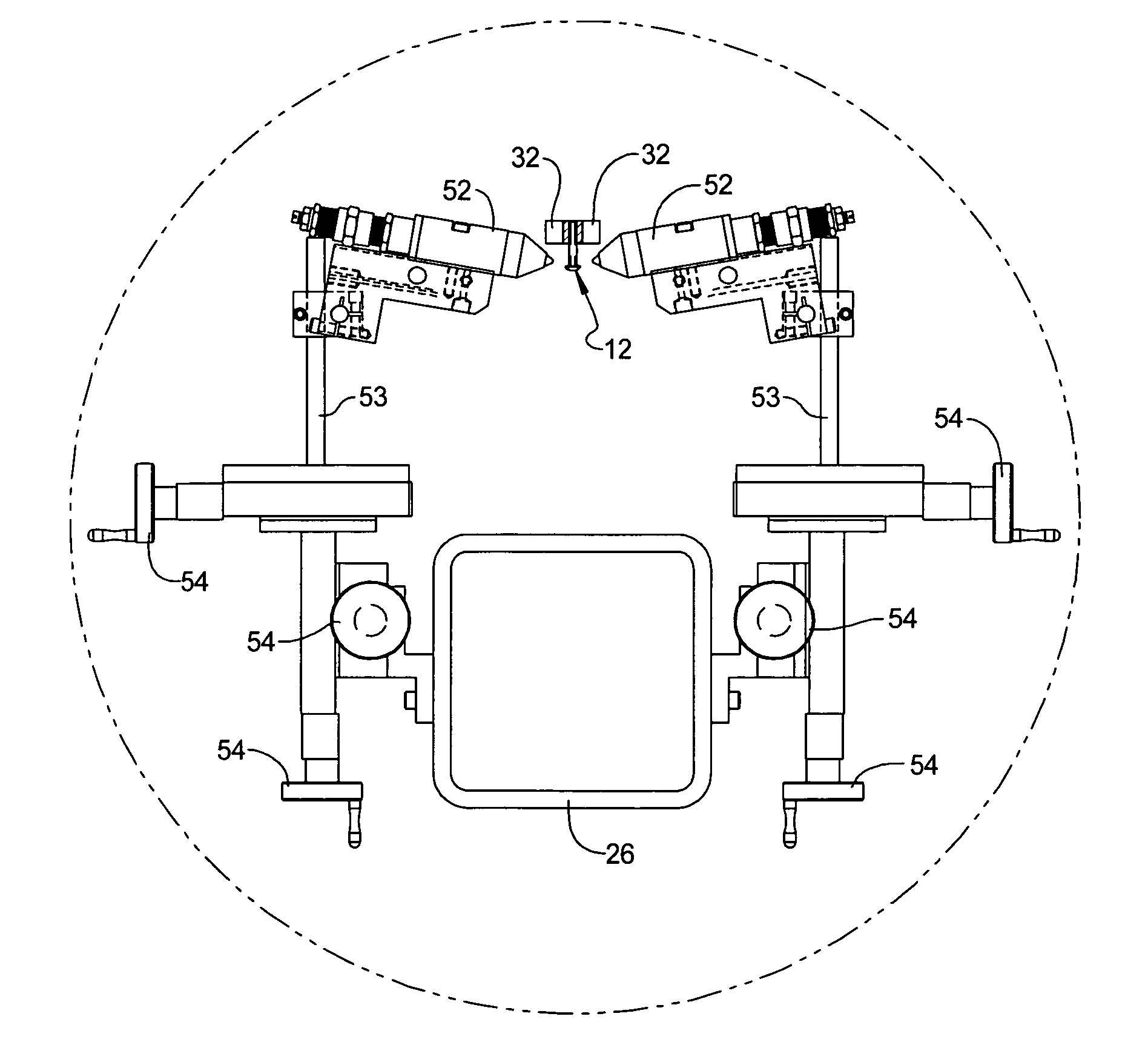
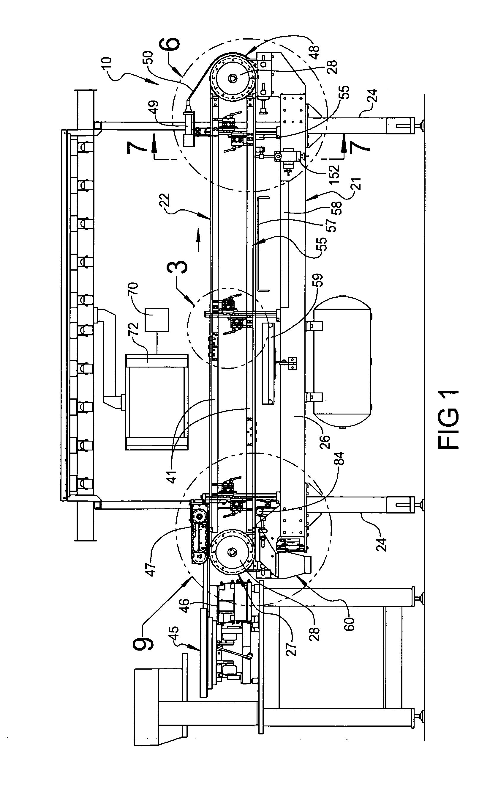
[0031]Referring now to the drawings, and in particular FIG. 1, one embodiment of an apparatus 10, according to the present invention, for coating fasteners, generally indicated at 12, is shown. The fasteners 12 are made of a non-magnetic or non-ferrous material such as stainless steel. The fasteners 12 may be of any suitable type or shape. As illustrated in FIG. 4A, in one embodiment, the fastener 12 has a head 14 extending radially and a shaft 16 extending axially from the head 14. In one embodiment, the fastener 12 has at least one, preferably a plurality of threads 18 disposed about and along the shaft 16. In one embodiment, the fastener 12 has a recess 20 extending axially into the head 14. It should be appreciated that the fastener 12, in other embodiments, may be odd shaped and that the threads 18 and recess 20 may be optional. It should be appreciated that the fasteners 12 are conventional and known in the art.

[0032]Referring to FIG. 1, the apparatus 10 includes a support fr...


PUM


Abstract

A coated fastener having a fastener and a coating disposed on a portion of the fastener. The coating is a liquid material applied to the fastener.

Description

CROSS-REFERENCE TO RELATED APPLICATION(S)[0001]The present application is a continuation of U.S. Ser. No. 11 / 511,539, filed Aug. 29, 2006.BACKGROUND OF THE INVENTION[0002]1. Field of the Invention[0003]The present invention relates generally to coating fasteners and, more specifically, to an apparatus and method for coating fasteners.[0004]2. Description of the Related Art[0005]It is known to apply a coating to fasteners with an apparatus such as automated machinery. An example of such an apparatus is disclosed in U.S. Pat. No. 5,918,727 to Wallace et al. In this patent, the apparatus provides a barrier coating on a portion of discrete objects such as fasteners utilizing a liquid coating material. The apparatus introduces either a plurality of loose or interconnected parts onto a magnetized conveyor system and optically senses when parts are present. When parts are sensed, the sensor triggers a discrete shot of liquid coating material such as a fluorocarbon to be deposited onto a pr...

Claims


Application Information

Patent Timeline
IPC IPC(8): F16B35/04
CPCB05B13/0221B05D1/12B05D2258/02B05D5/08B05D2202/00B05D3/0218
Inventor SNOW, GERALD F.DEFILLIPI, JAMES PATRICKBATURA, RAYMOND GERARD
Owner SNOW GERALD F
Why Eureka
Try Eureka