
Acute hemodialysis catheter assembly

a hemodialysis catheter and assembly technology, applied in the field of hemodialysis catheters, can solve the problems of poor flow performance, inefficient dialysis, and “recirculation” of blood

Active Publication Date: 2008-04-03
MOZARC MEDICAL US LLC
View PDF99 Cites 100 Cited by
  • Summary
  • Abstract
  • Description
  • Claims
  • Application Information

AI Technical Summary

Benefits of technology

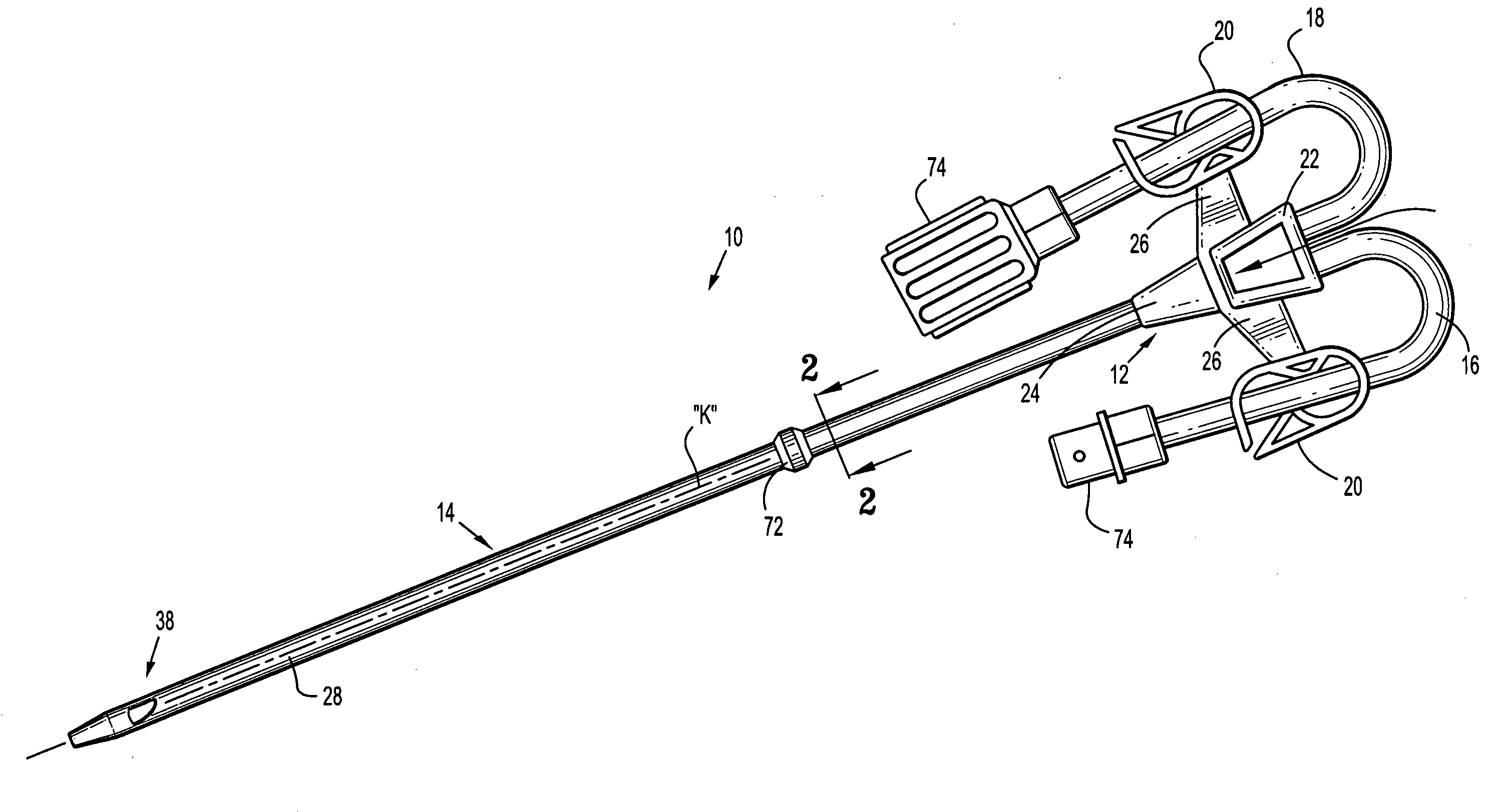
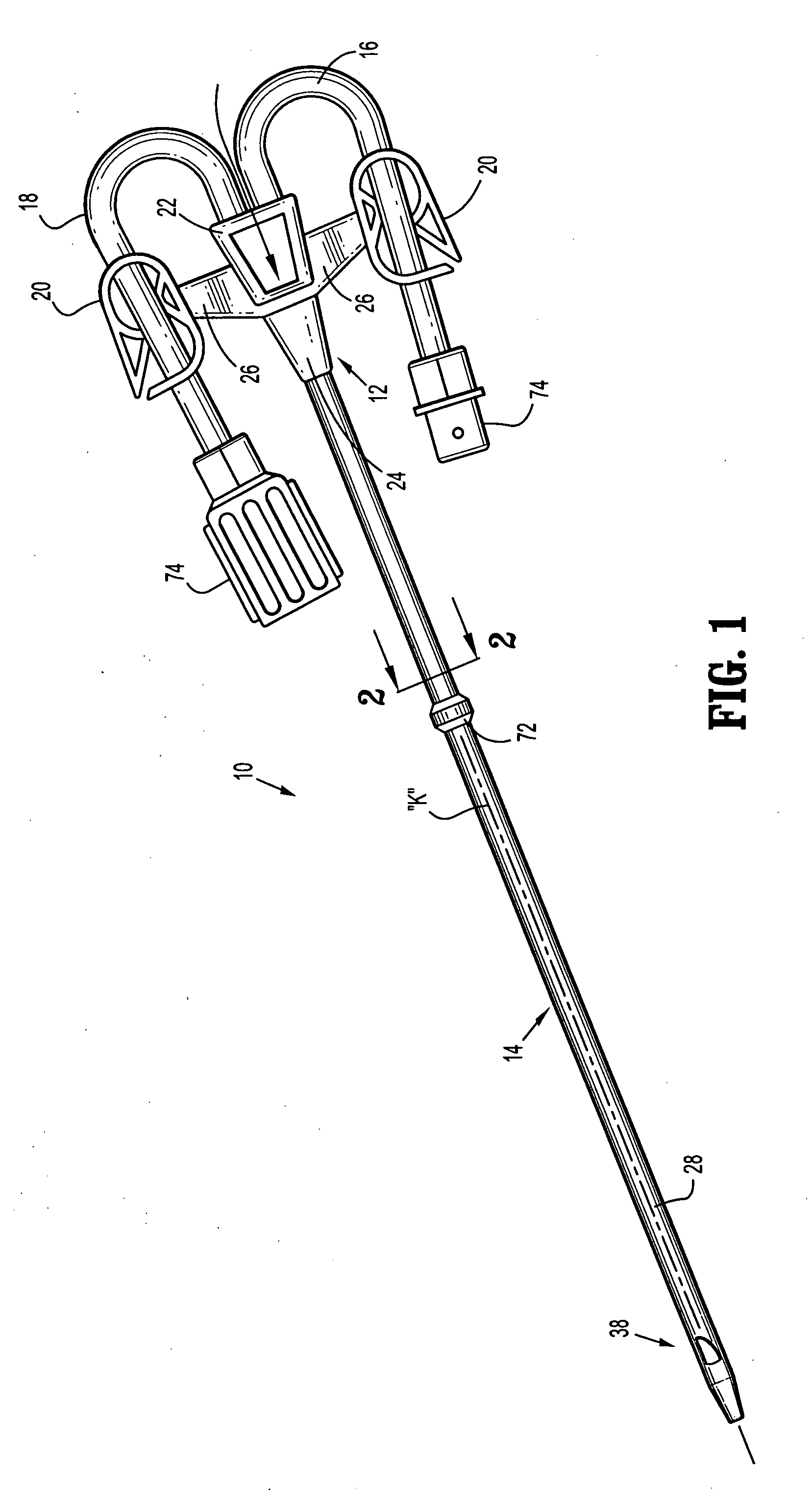
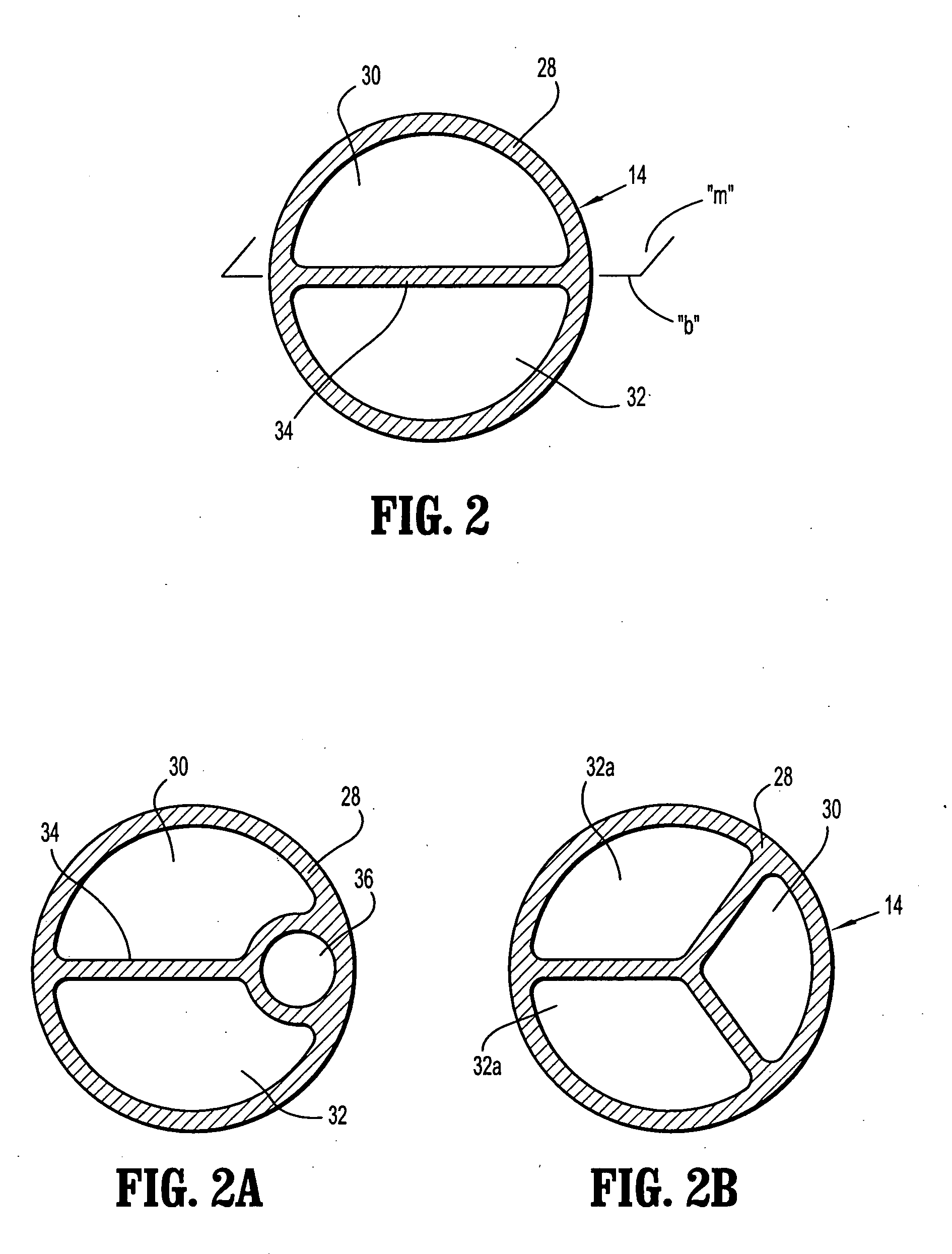
The present disclosure is directed to improvements in hemodialysis catheters and systems used therewith. The invention includes an elongate catheter member with an outer member having at least one longitudinal lumen and at least one elongate opening. The elongate opening has a transverse dimension that increases from proximal to distal, and is defined by wall portions that intersect at a proximal location and extend along the longitudinal axis. The elongate catheter member may also include first and second longitudinal lumens and corresponding elongate openings in fluid communication with the lumens. The elongate catheter member may also include a catheter tip member with a tapered configuration and a guide wire lumen therethrough. The technical effects of the invention include improved fluid flow and reduced blood clotting, as well as improved maneuverability and stability during use.

Problems solved by technology

Unfortunately, poor flow performance is a common problem with hemodialysis catheters, typically, due to occlusion resulting from fibrin sheath formation, thrombus formation and positional occlusion.
This, however, creates a situation where cleaned blood is expelled upstream relative to the catheter inlet, which undesirably increases the potential for clean blood to be drawn back into the catheter resulting in “recirculation” of the blood.
“Recirculation” creates inefficient dialysis by increasing treatment time to reach prescribed blood cleanliness levels.

Method used


Image

  • Acute hemodialysis catheter assembly
  • Acute hemodialysis catheter assembly
  • Acute hemodialysis catheter assembly

Examples


Embodiment Construction

[0027]The exemplary embodiments of the catheter and methods of use disclosed are discussed in terms of medical catheters for the administration of fluids relative to the body of a subject and, more particularly, in terms of an acute hemodialysis catheter. However, it is envisioned that the present disclosure may be employed with a range of catheter applications including surgical, diagnostic and related treatments of diseases, body ailments, of a subject. It is further envisioned that the principles relating to the catheter disclosed include employment with various catheter related procedures, such as, for example, hemodialysis, cardiac, abdominal, urinary, intestinal, in chronic and / or acute applications. Moreover, the catheter can be used for administration or withdrawal of fluids such as, for example, medication, saline, bodily fluids, blood and urine.

[0028]In the discussion that follows, the term “proximal” or “trailing” will refer to the portion of a structure that is closer to...


PUM


Abstract

A medical catheter includes an elongate catheter member defining a longitudinal axis, and a transverse axis transverse to the longitudinal axis, and having a proximal end and a distal end. The elongate catheter member includes an outer member and at least one longitudinal lumen within the outer member for passage of fluids. The outer member has an elongate opening therethrough in communication with the at least one longitudinal lumen and being spaced from the distal end and bound by wall portions of the outer member. The elongate opening permits fluids to pass between the at least one longitudinal lumen and locations external to the elongate catheter member, and defines a transverse dimension increasing from proximal to distal.

Description

BACKGROUND[0001]1. Technical Field[0002]The present disclosure relates to a catheter assembly, and, in particular, relates to a hemodialysis catheter adapted to facilitate bidirectional fluid flow.[0003]2. Description of the Related Art[0004]Catheters are flexible medical instruments intended for the withdrawal and introduction of fluids relative to body cavities, ducts and vessels. Catheters have particular application in hemodialysis procedures where blood is withdrawn from a blood vessel for treatment and subsequently returned to the blood vessel for circulation. Known hemodialysis catheters include multiple lumens, such as dual lumen or triple lumen catheters, permitting bi-directional fluid flow within the catheter whereby one lumen is dedicated for withdrawal of blood and the other lumen is dedicated for returning the treated blood to the vessel. During an exemplary hemodialysis procedure, a multiple lumen catheter is inserted into a body and blood is withdrawn through an arte...

Claims


Application Information

Patent Timeline
Patent Type & Authority Applications(United States)
IPC IPC(8): A61M25/00
CPCA61M25/0029A61M25/0032A61M1/3661A61M25/007A61M2025/0031A61M25/0069
Inventor BRAGA, RICHARD
Owner MOZARC MEDICAL US LLC
Learn More