Machining control method and machining information generating method for machine tool

a technology of machining information and control method, which is applied in the direction of computer control, program control, instruments, etc., can solve the problems machining efficiency not much improved in this method, and achieves the effect of high feeding rate, and reducing a feed ra

Inactive Publication Date: 2008-04-03
OKUMA CORP
View PDF12 Cites 10 Cited by
  • Summary
  • Abstract
  • Description
  • Claims
  • Application Information

AI Technical Summary

Benefits of technology

[0011]An object of the present invention is to provide a machining control method capable of carrying out complicated surface machining such as graining or the like, keeping the machining accuracy and machining efficiency, and to provide a machining information generating method to perform the machining control method.
[0017]According to the inventions described in claims 1 and 2, since the required movement distance is distributed to a main spindle head and an additional spindle, machining at a high feeding rate can be carried out without reducing a feed rate at a rough part. Thus, complicated surface machining such as graining or the like can be carried out without decreasing a machining accuracy and a machining efficiency.
[0018]According to the inventions described in claims 3 and 4, moving information of a main spindle head and an additional spindle can be easily, certainly generated based on data of a working surface. More particularly, in the invention described in claim 4, since a basic configuration surface of a working surface is used, it is not necessary to obtain data of a smoothed approximation surface, and thus the method can generate machining information easier than the method described in claim 3.

Problems solved by technology

Further, since machining must be carried out with a control of a large mass of a main spindle, it is still required to reduce a feed rate at a rough part.
Thus, machining efficiency does not much improve in this method.

Method used


Image

  • Machining control method and machining information generating method for machine tool
  • Machining control method and machining information generating method for machine tool
  • Machining control method and machining information generating method for machine tool

Examples


Embodiment Construction

[0027]Preferred embodiments of the present invention will be described below referring to the drawings.

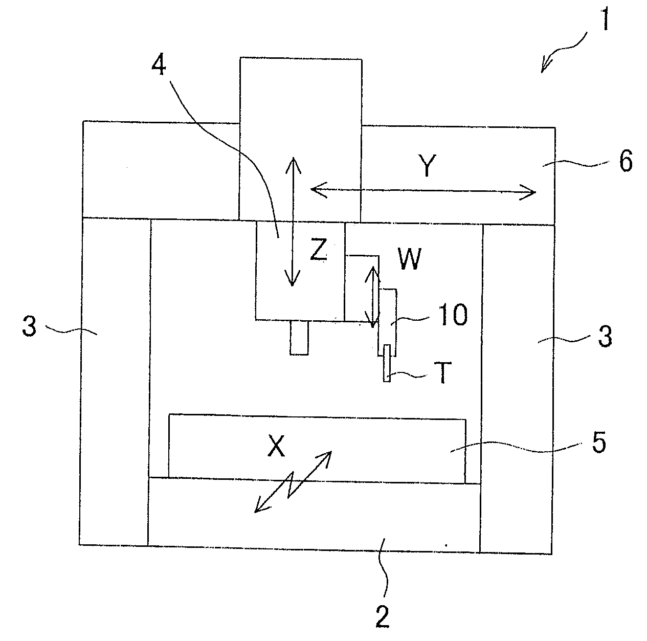
[0028]FIG. 1 is an explanation view to illustrate one example of a machine tool. A machine tool 1 includes a bed 2, a pair of columns 3 and 3 fixed at the bed 2, and a cross rail 6 provided between the columns 3 and 3, so as to have a rigid portal structure. The machine tool 1 includes a main spindle head 4 on a front surface of the cross rail 6, and the main spindle head 4 can slide in a Y direction (left and right directions), and move upwardly and downwardly along a Z direction (upper and lower directions). The main spindle head 4 includes an additional spindle 10 to which a tool T to machine a workpiece surface is attached, and the additional spindle 10 can slide in a W spindle direction (the vertical direction in this case) which is parallel to the Z spindle. The bed 2 includes a table 5 which can place a workpiece and slide along an X spindle direction (front and back directi...


PUM


Abstract

To provide a method to carry out complicated surface machining such as graining or the like without decreasing machining accuracy and machining efficiency. In a machine tool including a main spindle head capable of relatively moving in three perpendicular directions with respect to a workpiece and an additional spindle being provided at the main spindle head and capable of moving in a Z spindle direction, while the main spindle head relatively moves with respect to a working surface S of the workpiece along a smoothly curved surface R which is smoothed so as to be restricted within the movement distance in the moving direction of the additional spindle, the additional spindle moves by a difference between the working surface S and the smoothly curved surface R, and makes a tool T to machine the working surface S.

Description

[0001]This application claims the benefit of Japanese Patent Application Number 2006-268683 filed on Sep. 29, 2006, the entirety of which is incorporated by reference.BACKGROUND OF THE INVENTION[0002]1. Field of the Invention[0003]The present invention relates to a machining control method to perform a complicated surface machining to a workpiece by a machining tool such as a machining center or the like, and a machining information generating method to generate machining information given to a machine tool in order to perform the machining control method.[0004]2. Description of the Background Art[0005]When machining to give a complicated irregular configuration, e.g., graining, to a surface of a workpiece is carried out, for example, a machining control method using an NC control device described in the patent document 1 has been used. The NC control device includes a first input unit for inputting pre-texturing configuration data of a surface, a second input unit for inputting tex...

Claims


Application Information

Patent Timeline
Patent Type & Authority Applications(United States)
IPC IPC(8): G06F19/00B23C3/16B23Q5/34G05B19/4097
CPCB23Q1/601B23Q1/626G05B2219/50212G05B2219/49309G05B2219/50015G05B19/41B23C1/002B23C1/08
Inventor HASEBE, TAKAOHIOKI, KATSUYAWAKAOKA, SHUNSKE
Owner OKUMA CORP
Why Eureka
Try Eureka