Shifting arm

a technology of shifting arm and face, which is applied in the direction of mechanical control devices, process and machine control, instruments, etc., can solve the problems of low material consumption for the production of shifting arms of this type, and achieve the effects of increasing the resistance to wear of the face, high accuracy, and great material saving

Inactive Publication Date: 2008-04-10
SCHAEFFLER KG
View PDF0 Cites 3 Cited by
  • Summary
  • Abstract
  • Description
  • Claims
  • Application Information

AI Technical Summary

Benefits of technology

[0009] This object is achieved according to the invention by the shifting arm being a formed part which is formed from a thin sheet without cutting the sheet. The advantages of a shifting arm according to the invention in comparison with the prior art reside in the low costs for production, particularly in large-series and mass production. The consumption of material for the production of a shifting arm of this type is low. The weight of this shifting arm is reduced by up to 50% in comparison with the shifting arms described at the beginning. The thin material permits virtually unlimited designs. Use is made of forming processes without cutting, in particular processes for the cold-forming of sheets, such as rolling, drawing, stamping and punching. The required accuracies for functional dimensions, such as for the distance of the stop faces lying opposite each other in the shifting mouth, and functional faces, such as for the positioning and dimensioning of chamfers and roundings for the gentle introduction of the shifting finger in the shifting mouth, is, as a rule, obtainable only by the forming process or forming processes. Material-removing machining is unnecessary, as a rule.
[0013] The stop faces for the shifting finger lie, as a rule, opposite each other in the shifting mouth. Their distance from each other and alignment with respect to each other have to be realized with very high accuracy. Similarly, very exacting demands are placed on the dimensional accuracy of other functional faces in the shifting mouth, for example functional faces to rest a locking cylinder against. These accuracies for the functional dimensions, such as for the distance of the stop faces lying opposite each other in the shifting mouth from each other and their alignment with respect to each other, can be ensured, as a rule, without a material-removing finishing operation. Provision is therefore made by one refinement of the invention for the recess to be bounded at least by two stop faces, which lie plane-parallel opposite each other, face each other and are formed without cutting, on angled sections of the sheet, the distance between the stop faces lying opposite each other being realized, by machining without cutting, with an accuracy which permits a deviation from the desired value of the distance of at maximum 1 / 10 mm. Functional faces, such as the stop faces and such as the chamfers, which bound the shifting mouth or the stop faces and are required for the gentle introduction of the shifting finger into the shifting mouth, and roundings on body edges, are introduced without cutting. The surface of these functional faces is smooth and work-hardened on account of the stampings or the sizing. The resistance to wear of the faces is increased. Material-removing polishing is unnecessary.
[0014] A further refinement of the invention makes provision for the recess to be bounded at least by two stop faces, which lie opposite each other, face each other and are formed without cutting, on angled sections of the sheet. In this case, the shifting arm has at least one body edge which delimits the stop face at least at one side to form a further lateral face of the shifting arm and has a chamfer formed on it without cutting. A distance describing the chamfer in the cross section of the shifting arm between an edge, which bounds the stop face towards the chamfer, and an imaginary cut edge has an accuracy which permits a deviation from the desired value of the distance of at maximum 1 / 10 mm. The imaginary cut edge is a common cut edge, which is parallel to the edge, of the stop face, which is extended beyond the chamfer, together with the further lateral face of the shifting arm, which face is extended beyond the chamfer. The distance of the edge, which separates the stop face from the face produced by the chamfer, from the corner point of an imaginary, unbroken body edge is therefore very precise and can be realized more precisely than the distance brought about by material-removing machining.
[0015] The object is furthermore achieved by the shifting arm being a formed part which is formed without cutting from a thin sheet, the formed part being designed in a fork-shaped manner at one end and in this case being provided at the end with two prong-shaped projections. The shifting arm also has at least one edge on its outer contour that is formed by an angled sheet. Each of the projections is provided, on a section which is angled from the sheet of the shifting arm, at least with a stop face which lies opposite a further stop face lying opposite on the other of the projections. A shifting arm of this type can be produced with a great saving on material and has a low weight. The design possibilities are diverse.
[0017] In one refinement of the invention, the shifting arm is provided with at least one formation of bead-like design. To prevent the shifting arm from buckling and to increase the torsional rigidity, the shifting arm is provided on the different wall sections in a manner corresponding to its purpose with one or more beads or with laminations, stampings, protrusions of the sheet or bending over of the sheet at the edges, which are produced without cutting. Also very effective in this respect is an edge which is peripherally reinforced as far as possible on the shifting arm, which is essentially of flat design. This reinforced edge is produced by a bead or by a sheet which is angled away at the edge from the flat base body.
[0019] Finally, provision is made with one refinement of the invention for the shifting arm to have at least one formation of bead-like design on at least one of the wall sections. To prevent the shifting arm from buckling and to increase the torsional rigidity, the shifting arm is provided on at least one or individual or all of the different wall sections in accordance with its use with one or more beads or with laminations, stampings, protrusions of the sheet or bending over of the sheet at the edges, which are produced without cutting.

Problems solved by technology

The consumption of material for the production of a shifting arm of this type is low.

Method used


Image

  • Shifting arm
  • Shifting arm
  • Shifting arm

Examples


Embodiment Construction

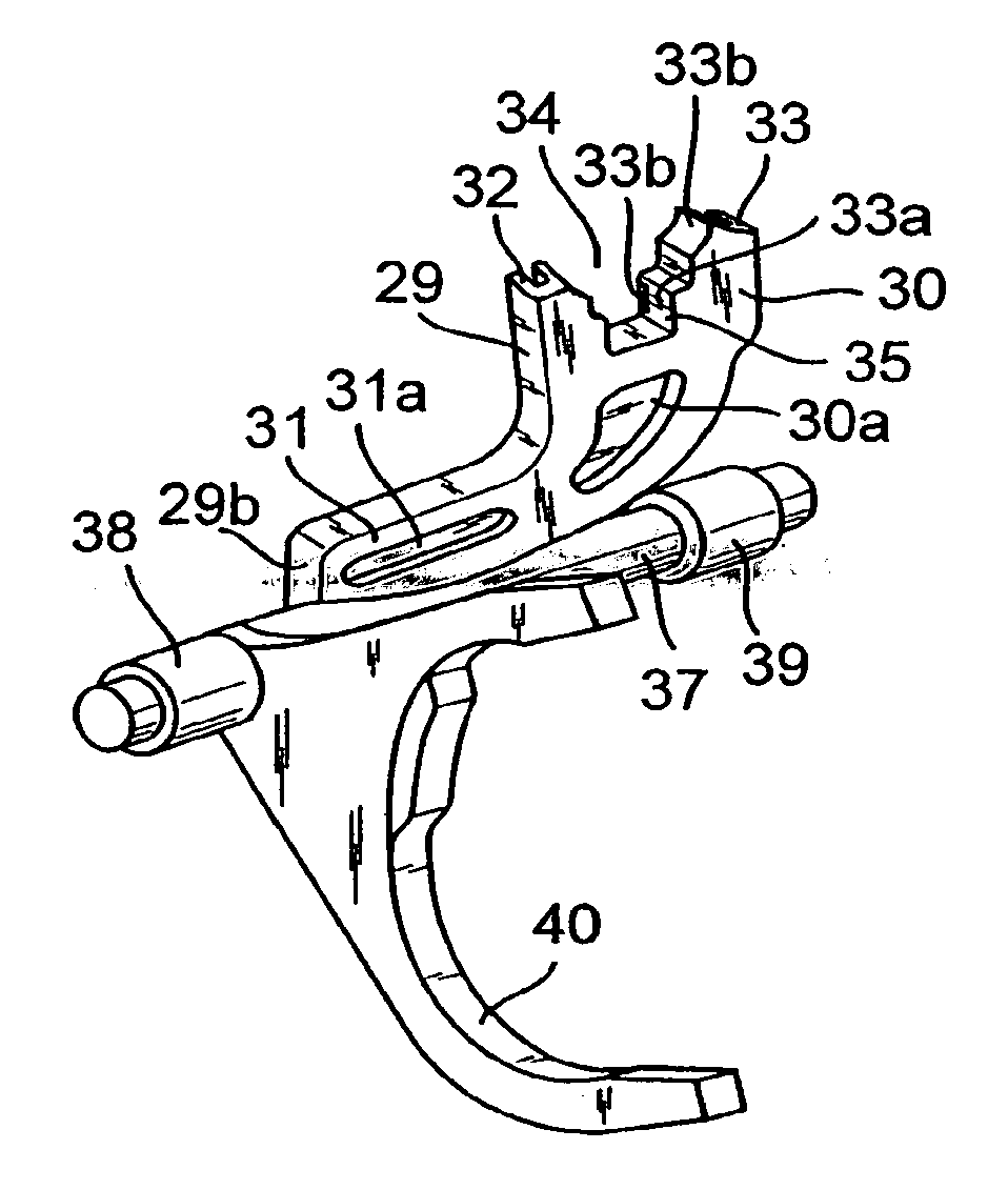
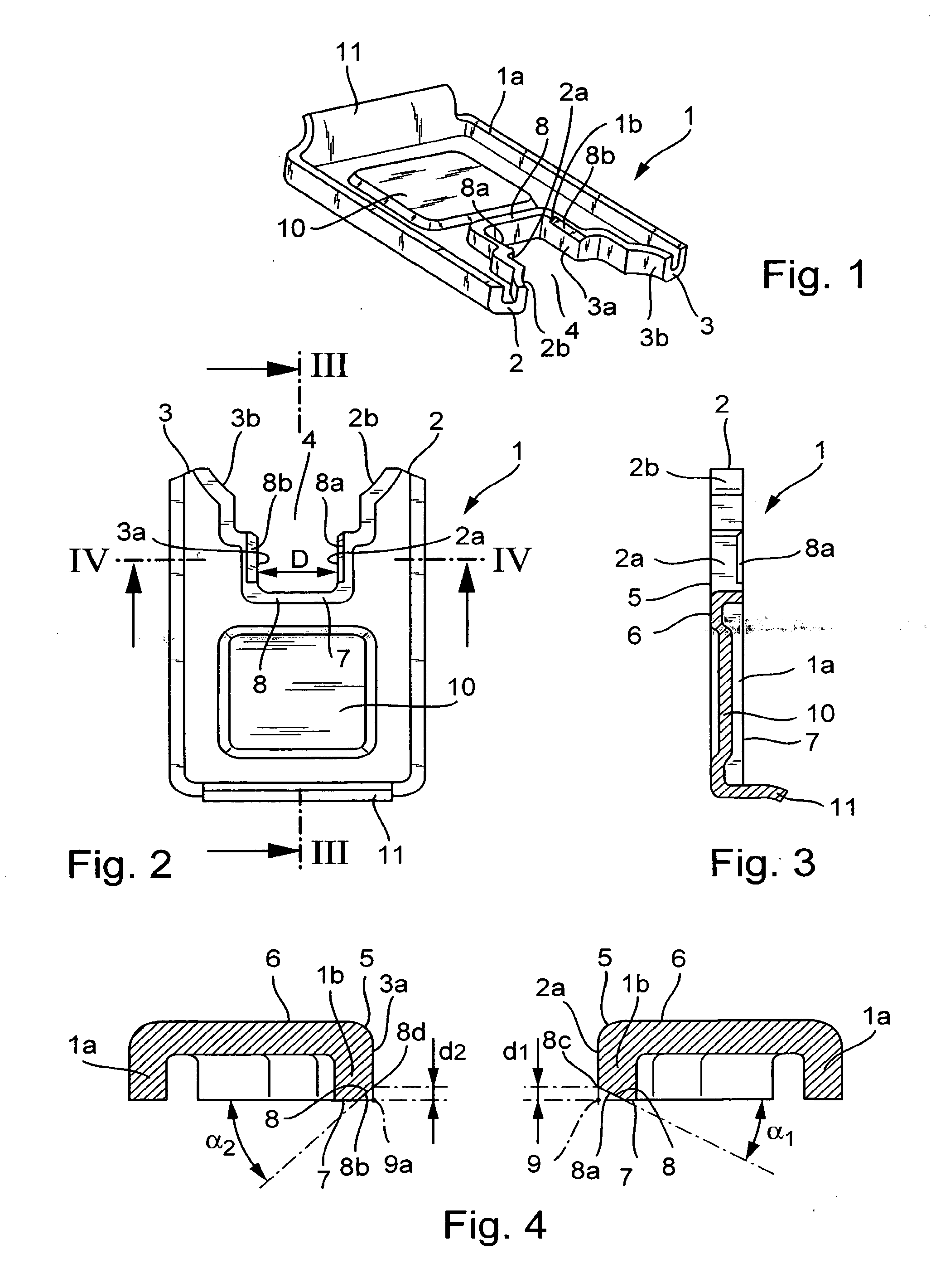
[0035] FIGS. 1 to 4 illustrate a shifting arm. The shifting arm 1 is formed from a flat formed part which is formed without cutting from a thin sheet of 2 mm. The formed part has a fork-shaped design and has two prong-shaped projections 2 and 3. The projections 2 and 3 bound a recess 4. The recess 4 is partially bounded by four stop faces 2a, 2b, 3a, 3b lying opposite one another. A shifting finger (not illustrated) strikes against the stop faces 2a and 3a. The stop faces 2b and 3b, which are designed lying opposite each other, are, in a locking position, a stop for a locking cylinder or locking pin (not illustrated). Each of the stop faces 2a, 2b, 3a, 3b is formed on a section 1b which hems the recess 4 and is angled away from meaning out of the plane of the sheet or the plane of the shifting arm 1 or of the projections 2 and 3. The stop faces 2a and 3a face each other and are aligned plane-parallel to each other. The clear distance D between the stop faces 2a and 3a is realized, b...


PUM


Abstract

A shifting arm for transmitting shifting movements is a formed part which is formed without cutting from a thin sheet. It includes a mouth recess in from an edge of the sheet, and stop faces are formed along the edges of the recess and out of the plane of the sheet.

Description

CROSS REFERENCE TO RELATED APPLICATIONS [0001] The present application is a continuation of U.S. patent application Ser. No. 11 / 441,637, filed Apr. 26, 2006, which is a continuation of U.S. patent application Ser. No. 10 / 818,247, filed Apr. 5, 2004, which is a continuation of International Application PCT / EP2002 / 10915, filed Sep. 28, 2002, which claims priority of German application No. 101 48 980.2, filed Oct. 4, 2001, the entire contents of which are incorporated herein by reference.FIELD OF THE INVENTION [0002] The invention relates to a sheet-metal shifting arm for transmitting shifting movements. BACKGROUND OF THE INVENTION [0003] Shifting arms of this type are arranged fixedly on shifting elements, such as shifting shafts or shifting forks. The shifting shafts sit displaceably and / or pivotably in the transmission. The shifting forks sit, for example, displaceably and / or pivotably on a shifting rail. The shifting elements are displaced and / or pivoted by means of a shifting fing...

Claims


Application Information

Patent Timeline
Patent Type & Authority Applications(United States)
IPC IPC(8): G05G1/04F16H63/32
CPCF16H63/32F16H2063/322Y10T74/20Y10T74/20582F16H2063/327
Inventor SEUFERLING, STEPHANDOPPLING, HORSTWERNER, STEFANSCHUBEL, RAINER
Owner SCHAEFFLER KG
Why Eureka
Try Eureka