Hanger and display

a technology of hanging rods and slats, which is applied in the field of hanging rods and displays, can solve the problems of increasing the screen size of thin display televisions, putting a heavy burden on operators, and reducing the service life of operators, so as to achieve easy wall hanging operation and easy alignment. , the effect of reducing the burden

Inactive Publication Date: 2008-04-10
PANASONIC CORP
View PDF13 Cites 33 Cited by
  • Summary
  • Abstract
  • Description
  • Claims
  • Application Information

AI Technical Summary

Benefits of technology

[0010] It is an object of the present invention to solve the problems described above and to provide a hanger that enables an easy alignment at the time of hanging a display main body on a wall, and a display including the same.
[0013] In accordance with the present invention, at a position adjacent to that in which the projecting portion attached to the main body of the display (the display main body) and the support member are to be connected, the projecting portion can be placed temporarily on the support member. At this time, part of the support member is caught between the stopper of the projecting portion and the display main body. Thus, the display main body is held stably, so that a heavy burden is not put upon the operator. Consequently, compared with the conventional case, it is easier to align the projecting portion and the support member, resulting in an easier wall-hanging operation of the display main body.

Problems solved by technology

Furthermore, the operator needs to make such alignment while holding the television main body, and this puts a heavy burden upon the operator.
Moreover, this operation becomes more difficult with an increase in the screen size of the thin display television.

Method used


Image

  • Hanger and display
  • Hanger and display
  • Hanger and display

Examples


embodiment 1

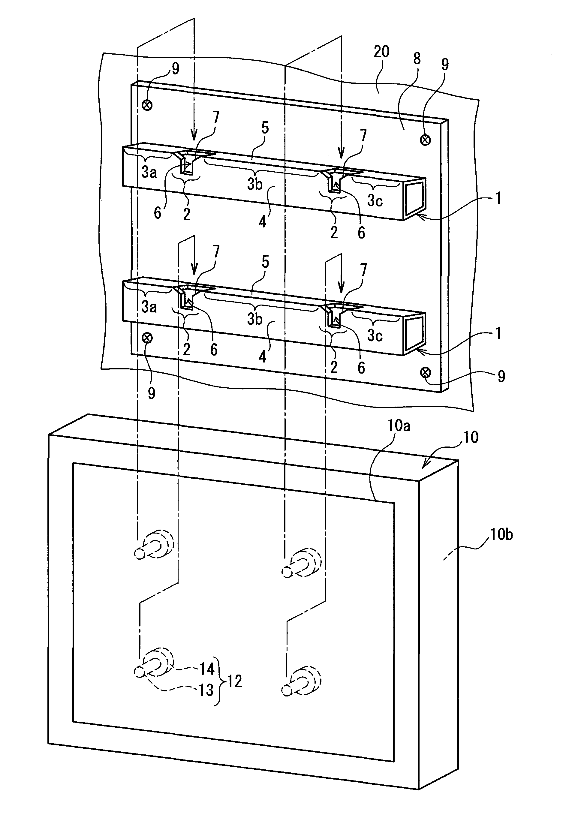
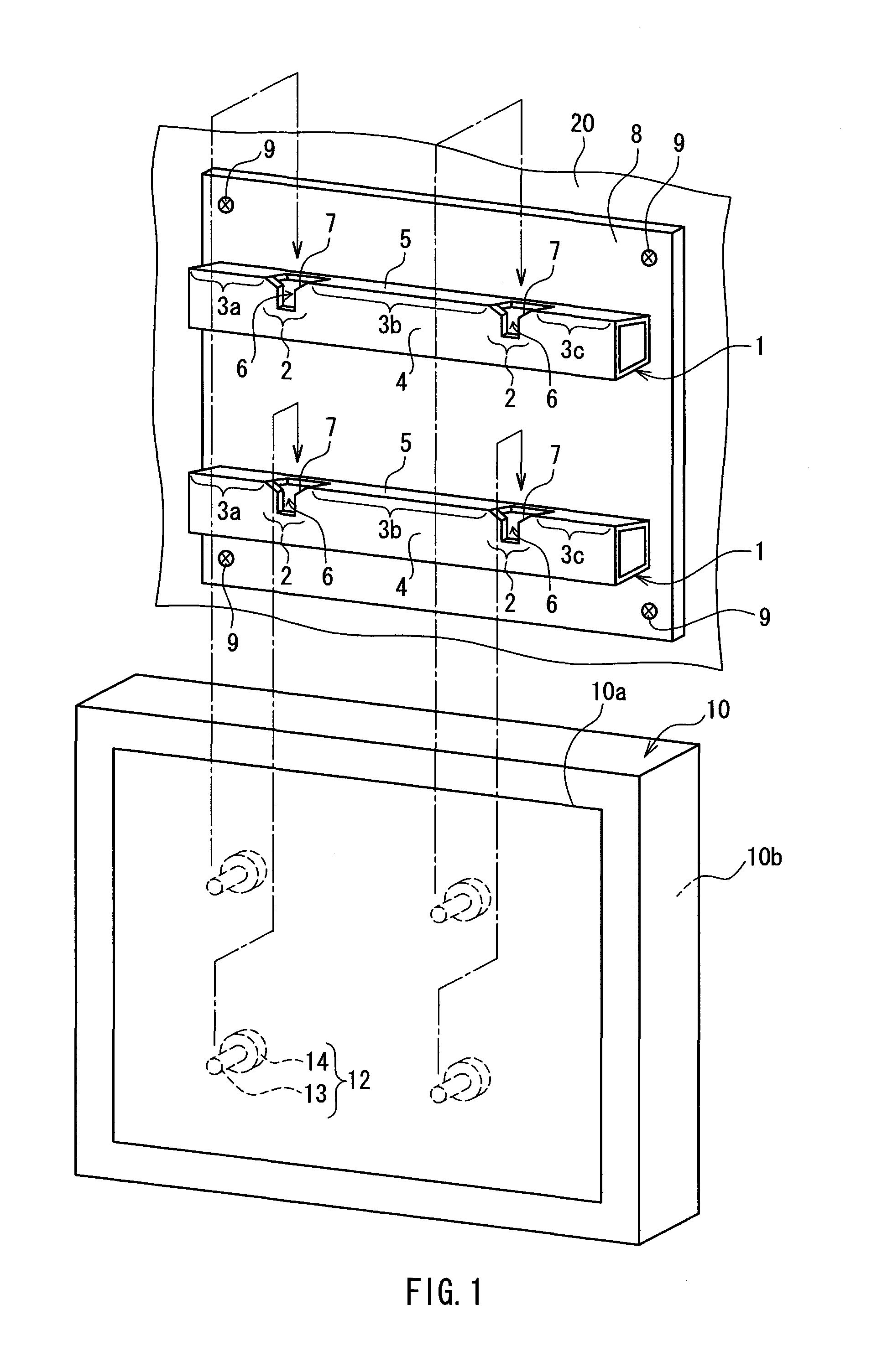
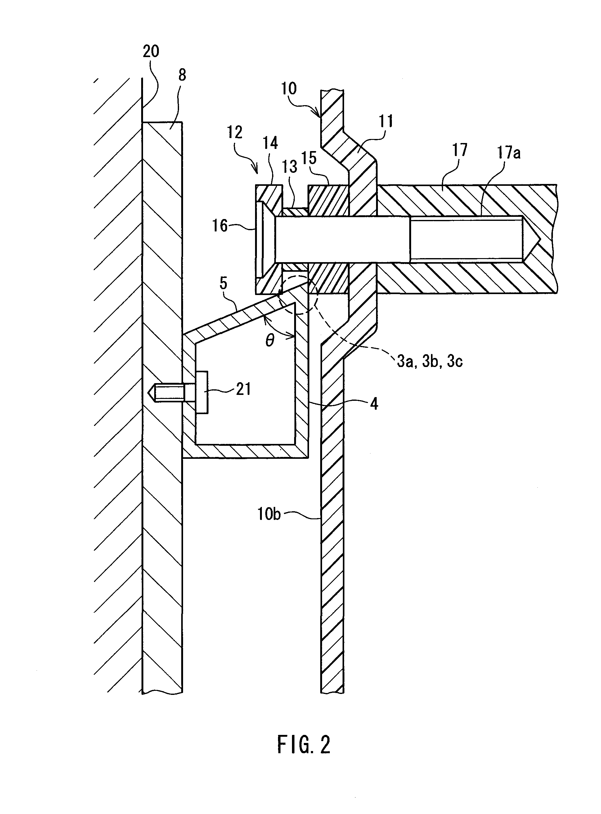
[0037] The following is a description of a hanger and a display according to Embodiment 1 of the present invention with reference to FIGS. 1 to 6. First, the structure of the hanger according to Embodiment 1 of the present invention will be described with reference to FIGS. 1 and 2. FIG. 1 is a perspective view showing the structure of the hanger and the display according to Embodiment 1 of the present invention. FIG. 2 is a cross-sectional view showing the structure of the hanger shown in FIG. 1. Furthermore, FIG. 2 shows the state in which a display main body 10 is placed temporarily on a support member 1.

[0038] As shown in FIG. 1, the hanger is used for hanging the display main body 10 on the wall, and includes projecting portions 12 that are mounted on a surface 10b (a rear surface) of the display main body 10 opposite to a display screen 10a, and the support members 1 connected to the projecting portions 12. This hanger and the display main body 10 constitute the display accor...

embodiment 2

[0064] Next, a hanger and a display according to Embodiment 2 of the present invention will be described with reference to FIGS. 7 to 10. FIG. 7 is a plan view showing support members constituting the hanger according to Embodiment 2 of the present invention. FIG. 8 is an exploded perspective view showing an enlarged portion of the support members shown in FIG. 7. FIG. 9 is a cross-sectional view showing the structure of the support member shown in FIG. 7.

[0065] As shown in FIG. 7, in Embodiment 2 of the present invention, support members 51a and 51b are used in place of the support members 1 shown in FIG. 1. In Embodiment 1, two support members 1 are attached to the wall surface 20 in parallel with each other, whereas in Embodiment 2 of the present invention, the support members 51a and 51b are attached to the wall surface 20 in such a manner as to intersect each other. Furthermore, projecting portions to which the support members 51a and 51b are to be connected are similar to the...

embodiment 3

[0075] Now, a hanger and a display according to Embodiment 3 of the present invention will be described with reference to FIGS. 11 to 13. FIG. 11 is a perspective view showing a support member constituting the hanger according to Embodiment 3 of the present invention. FIG. 12 is a cross-sectional view showing the structure of the support member shown in FIG. 11. FIG. 13 is a side view showing the support member shown in FIG. 11.

[0076] As shown in FIG. 11, in Embodiment 3 of the present invention, a support member 61 is used in place of the support member 1 shown in FIG. 1. The support member 61 is constituted by a portion 64 that extends in parallel with a horizontal direction and portions 65 and 66 that extend in parallel with a vertical direction when the support member 61 is fixed to the wall surface 20. The support member 61 thus has an inverted-U shape (in other words, a shape obtained by connecting two Ts that are next to each other) when viewed from a front side.

[0077] More...


PUM


Abstract

A hanger that enables an easy alignment at the time of hanging a display main body on a wall, and a display including the same are provided. The hanger includes a projecting portion that is attached to a rear surface of the display main body, and a support member that is fixed to a wall surface and connected to the projecting portion so as to support the display main body. The projecting portion includes a shaft that sticks out from the rear surface and a stopper that is attached to a tip of the shaft. The support member includes a connector to be connected to the projecting portion and a temporary holder on which the projecting portion is placed temporarily before the projecting portion and the connector are connected. The temporary holder is located at a position adjacent to the connector and formed so as to be caught between the stopper and the rear surface when the projecting portion is placed temporarily.

Description

BACKGROUND OF THE INVENTION [0001] 1. Field of the Invention [0002] The present invention relates to a hanger for hanging a main body of a display such as a plasma television and a liquid crystal television, and a display including the same. [0003] 2. Description of Related Art [0004] Recently, in the field of a television receiver (hereinafter referred to as a “television”), a rapid generation shift from a CRT television to a thin display television such as a plasma television and a liquid crystal television has been taking place. The thin display television is literally thinner and lighter than the CRT television. With these features, the thin display television not only is placed on a television stand similarly to the conventional CRT television, but also is hung on a wall in some cases (see for example, JP 11(1999)-201386A. [0005] Hereinafter, the case of hanging the thin display television on a wall will be described with reference to FIG. 15. FIG. 15 is a perspective view show...

Claims


Application Information

Patent Timeline
Patent Type & Authority Applications(United States)
IPC IPC(8): A47G1/24
CPCF16M13/02F16M11/10
Inventor MATSUI, HITOSHI
Owner PANASONIC CORP
Why Eureka
Try Eureka