Shimming of magnet systems

Inactive Publication Date: 2008-04-10
SIEMENS PLC
View PDF10 Cites 9 Cited by
  • Summary
  • Abstract
  • Description
  • Claims
  • Application Information

AI Technical Summary

Benefits of technology

[0006] It is preferable, from the standpoints of cost and reliability, to limit the number of coils used, and thus it is preferred where possible to avoid the use of secondary coils. However, there is now a tendency to fabricate the primary coils by winding them into pre-defined journals of a common former, and to encapsulate them. This means

Problems solved by technology

However, there is now a tendency to fabricate the primary coils by winding them into pre-defined journals of a common former, and to encapsulate the

Method used


Image

  • Shimming of magnet systems
  • Shimming of magnet systems
  • Shimming of magnet systems

Examples


Embodiment Construction

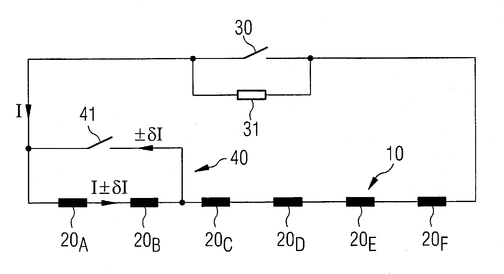
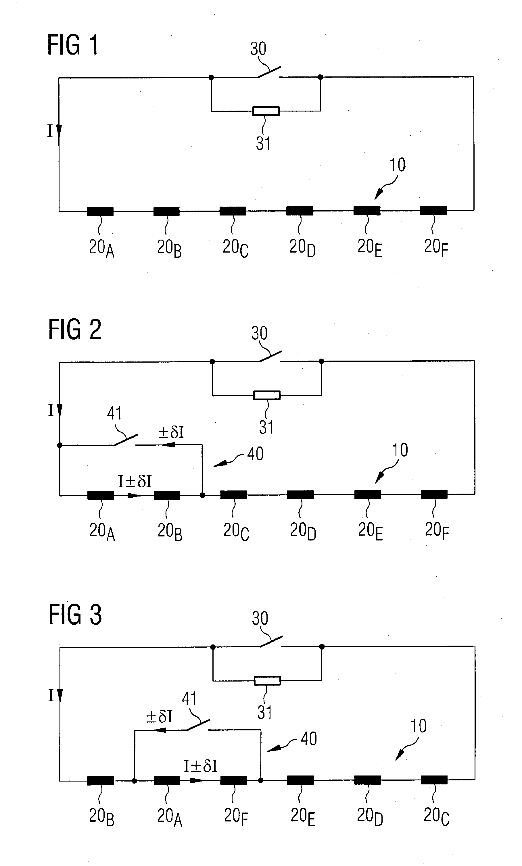
[0014]FIG. 1 illustrates a conventional arrangement wherein all coil portions 20A to 20F are electrically connected in series, and carry a common electrical current l.

[0015] A known primary coil system 10 of a powerful superconductive magnet intended for use in an MRI system typically has a coil system including a number of coil portions 20A, to 20F all connected in series, and across which is connected a superconducting switch 30 by means of which a large current (in the order of several hundred amperes) can be caused to flow through the primary coil system 10. A resistor 31 is conventionally connected across the superconducting switch, to protect the switch. The coil portions 20 may be wound upon a common, pre-molded former (not shown) and encapsulated thereon. As mentioned above, it is not readily or economically possible, with such a coil system, to pre-distort the powerful magnetic field generated by the primary coil system 10 by changing the physical position of one or more o...


PUM


Abstract

A primary magnetic coil system is composed of multiple coil portions supported in predetermined relative positions, the multiple coil portions being electrically connected in series and carrying a common primary coil current during operation. The system has a corrective component that selectively causes a corrective electric current to be supplied to a subset of the coil portions.

Description

BACKGROUND OF THE INVENTION [0001] 1. Field of the Invention [0002] The present invention relates to improving the homogeneity of magnetic fields generated in electromagnets, particularly magnetic fields generated by superconducting magnet arrangements utilized in magnetic resonance imaging (MRI) systems. [0003] 2. Description of the Prior Art [0004] It is well known that, in order to achieve, over the field of view (FOV) of an MRI system, the high degree of field homogeneity required of the magnetic fields employed, corrective measures need to be taken, since the powerful fields as generated by the primary superconducting magnet coils can be inhomogeneous to an unacceptable extent. [0005] A commonly used corrective measure, called “shimming” involves the measurement of the characteristics of the magnetic field to identify its degree of spatial homogeneity and the calculation of a specific field pre-distortion necessary to correct inhomogeneities to a prescribed extent. This field p...

Claims


Application Information

Patent Timeline
IPC IPC(8): H01F6/04H01F5/00H01F7/06
CPCG01R33/3875G01R33/3815G01R33/387
Inventor BEASLEY, PAUL
Owner SIEMENS PLC
Why Eureka
Try Eureka