Device for controlling a driven moving element, for example, a door

a technology of moving elements and devices, applied in the direction of door/window fittings, burglar alarms by opening, instruments, etc., can solve the problem of collision between persons and the door that has not been completely opened regularly

Active Publication Date: 2008-04-10
CEDES AG
View PDF29 Cites 9 Cited by
  • Summary
  • Abstract
  • Description
  • Claims
  • Application Information

AI Technical Summary

Benefits of technology

[0015] In the case of a plurality of moving elements, it is preferred if all the moving elements can be controlled independently. The best possible movement sequences can thereby be obtained for the individual moving elements.
[0016] For the case where a plurality of driven moving elements that cannot be moved independently are provided, it is advantageous if the smallest distance determined to a moving element, in particular to the front edge of a moving element, is crucial for the control of the moving elements.

Problems solved by technology

In winter, however, the problem arises of keeping a sliding door closed, if possible, in order to avoid heat losses from rooms that can be entered via the sliding door.
Since persons expect the door to open completely, a collision between persons and the door that has not been completely opened regularly occurs.

Method used


Image

  • Device for controlling a driven moving element, for example, a door
  • Device for controlling a driven moving element, for example, a door
  • Device for controlling a driven moving element, for example, a door

Examples


Embodiment Construction

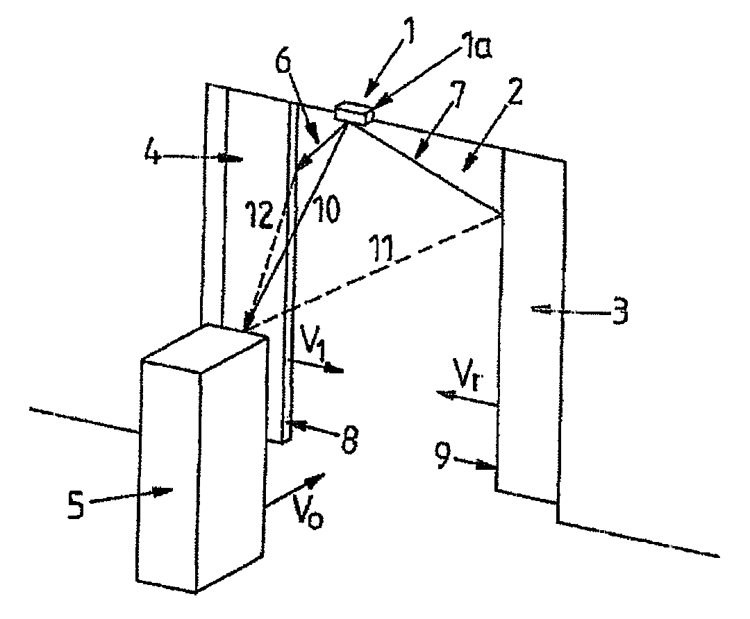
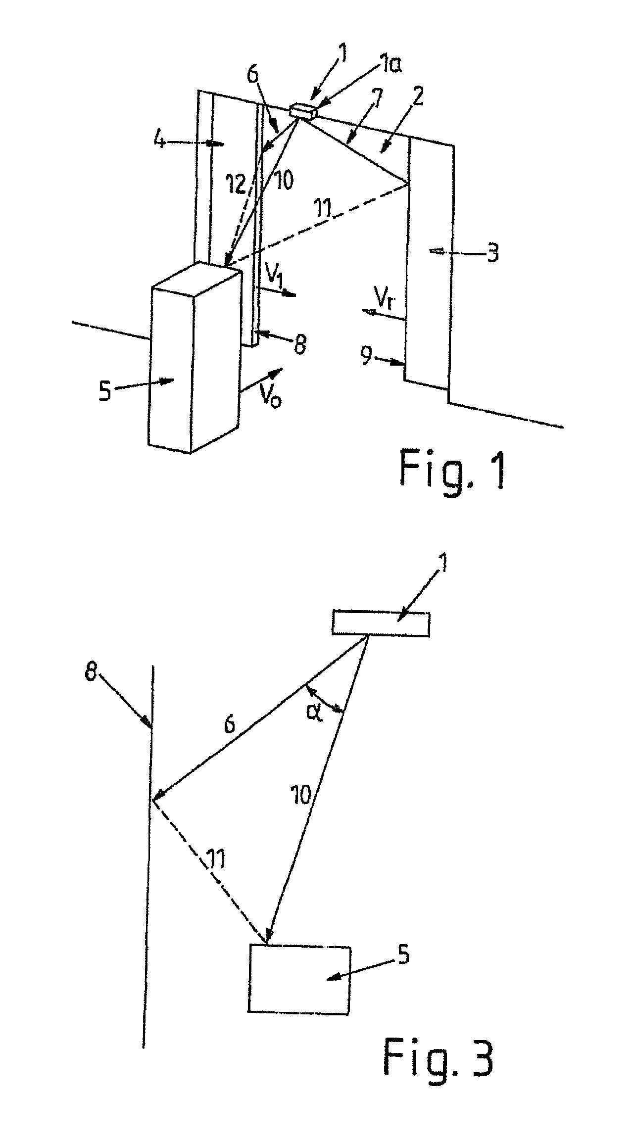
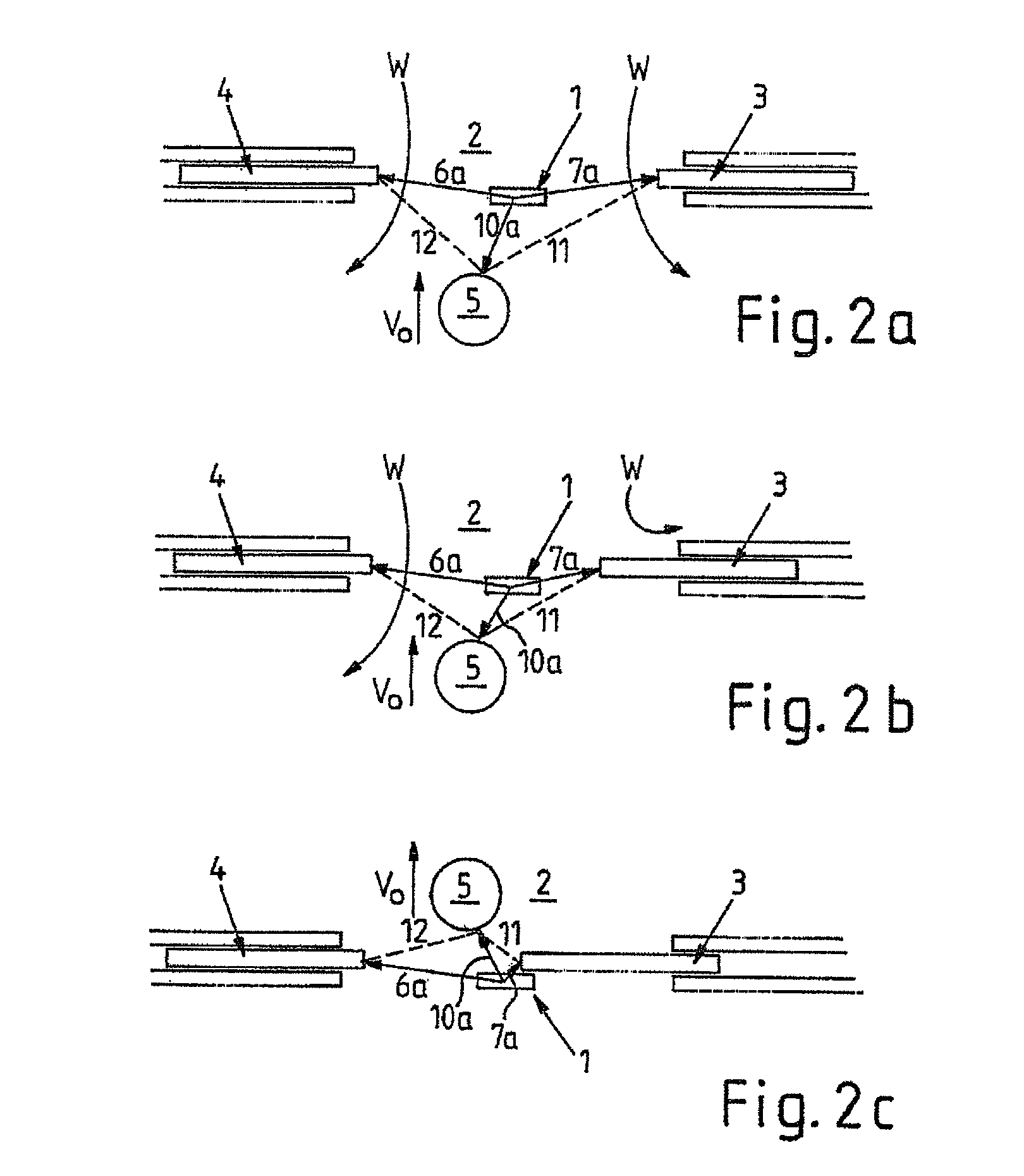
[0028]FIG. 1 illustrates an optical door sensor arrangement 1 on a sliding door 2 with an optical sensor 1a above the sliding door 2. Leaves 3, 4 of the sliding door 2 are partly open and close precisely with velocities Vl and Vr. An object 5, for example a person, is moving toward the sliding door 2 at a velocity Vo.

[0029] The door sensor arrangement 1 detects 3D images of its surroundings. A built-in computer (not illustrated) analyzes the images and determines therefrom the position and velocity of the sliding door leaves 3, 4 and of the object 5. FIG. 1 illustrates vectors 6, 7 and 10 for three pixels from an image determined in this way. The vectors 6 and 7 are directed at pixels of edges 8, 9 of the respective leaves 3, 4 and the vector 10 is directed at a pixel of the object 5. Normally, the edges 8, 9 of the leaves 3, 4 and also the object 5 are detected simultaneously over a plurality of pixels. A higher accuracy and hence reliability can thereby be obtained. However, the ...


PUM


Abstract

A device for controlling a driven moving element including an electronic unit with an object sensor. According to the invention, the electronic unit is designed, by means of the object sensor, to determine an object distance between the driven moving element and an object in the region of the moving element and to control the movement of the moving element depending on said object distance.

Description

CROSS REFERENCE TO RELATED APPLICATIONS [0001] This application is a continuation of International Application No. PCT / EP2006 / 003577 having an international filing date of Apr. 19, 2006, which designated the United States, and claims the benefit under 35 USC §119(a)-(d) of German Application No. 10 2005 018 231.3, filed Apr. 19, 2005, and German Application No. 10 2005 023 774.6, filed May 19, 2005, the entireties of which are incorporated herein by reference.FIELD OF THE INVENTION [0002] The present invention relates to a device for controlling a driven moving element, for example a door. BACKGROUND OF THE INVENTION [0003] In known embodiments, the closing of sliding doors is monitored by means of sensors which can detect an object in the path of movement of a door leaf, that is to say that the sensor ascertains whether or not an object is present. A further differentiation does not take place. [0004] Accordingly, when an object is detected, the sliding door is always opened comple...

Claims


Application Information

Patent Timeline
Patent Type & Authority Applications(United States)
IPC IPC(8): G08B13/08
CPCE05Y2400/356E05Y2400/415E05F15/73E05Y2900/132E05Y2400/45E05Y2400/322
Inventor ALBERS, BASDE COI, BEATNEBIKER, PETER
Owner CEDES AG
Why Eureka
Try Eureka