
Display Device Comprising a Panel Acoustic Transducer, and Transparent Panel Acoustic Transducer

a technology of panel acoustic transducer and display device, which is applied in the direction of transducer diaphragm, electromechanical transducer, diaphragm construction, etc., can solve the problems of increasing the complexity of the device and its manufacture, affecting the overall impression, and undesirable holes, etc., to achieve the effect of simple design

Inactive Publication Date: 2008-04-10
KONINKLIJKE PHILIPS ELECTRONICS NV
View PDF6 Cites 32 Cited by
  • Summary
  • Abstract
  • Description
  • Claims
  • Application Information

AI Technical Summary

Benefits of technology

[0009]It is an object of the invention to provide a display device having a panel acoustic transducer with a relatively simple design which at least reduces one or more of the above-mentioned problems.
[0016]Furthermore, the freely vibrating areas are excited very efficiently, because the side area of the thin panel is provided with an exciter.
[0018]In a preferred embodiment, the thin panel has at least two side areas at opposing sides of the panel, each side area being provided with an exciter or receiver. This increases the efficiency and also makes it possible to produce stereo sound.
[0020]Such stiffening parts increase the stiffness of the supporting panel, allowing a reduction of weight. In preferred embodiments, the stiffening parts may be used as a mount for other elements, such as a display screen.

Problems solved by technology

These holes are undesirable.
This means that these loudspeakers have to be separate parts, rather than parts of the front panel itself, which increases the complexity of the device and of its manufacture.
Moreover, they are distinguishable as separate parts, which has a distracting effect on the overall impression of the design.
However, this design has a negative influence on the quality of the image.
Consequently, reflections of lamps and other objects in this front panel also vibrate and thus distract the viewer, because visible artefacts are created.
Furthermore, the exciters required to generate the sound have to be on the side of the front panel so as to allow the display screen to remain visible, which makes the excitation not very efficient, especially at low frequencies.

Method used


Image

  • Display Device Comprising a Panel Acoustic Transducer, and Transparent Panel Acoustic Transducer
  • Display Device Comprising a Panel Acoustic Transducer, and Transparent Panel Acoustic Transducer
  • Display Device Comprising a Panel Acoustic Transducer, and Transparent Panel Acoustic Transducer

Examples


Embodiment Construction

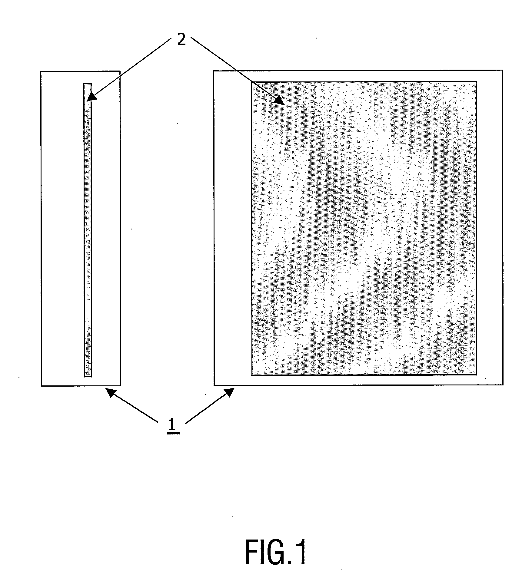
[0030]FIG. 1 shows schematically a display device 1 comprising a display screen 2 in an envelope 3. Within the scope of the present invention, ‘display screen’ may be any display, for instance, an LCD or a PDP or any other flat type display, or a CRT display, i.e. any apparatus for displaying an image.

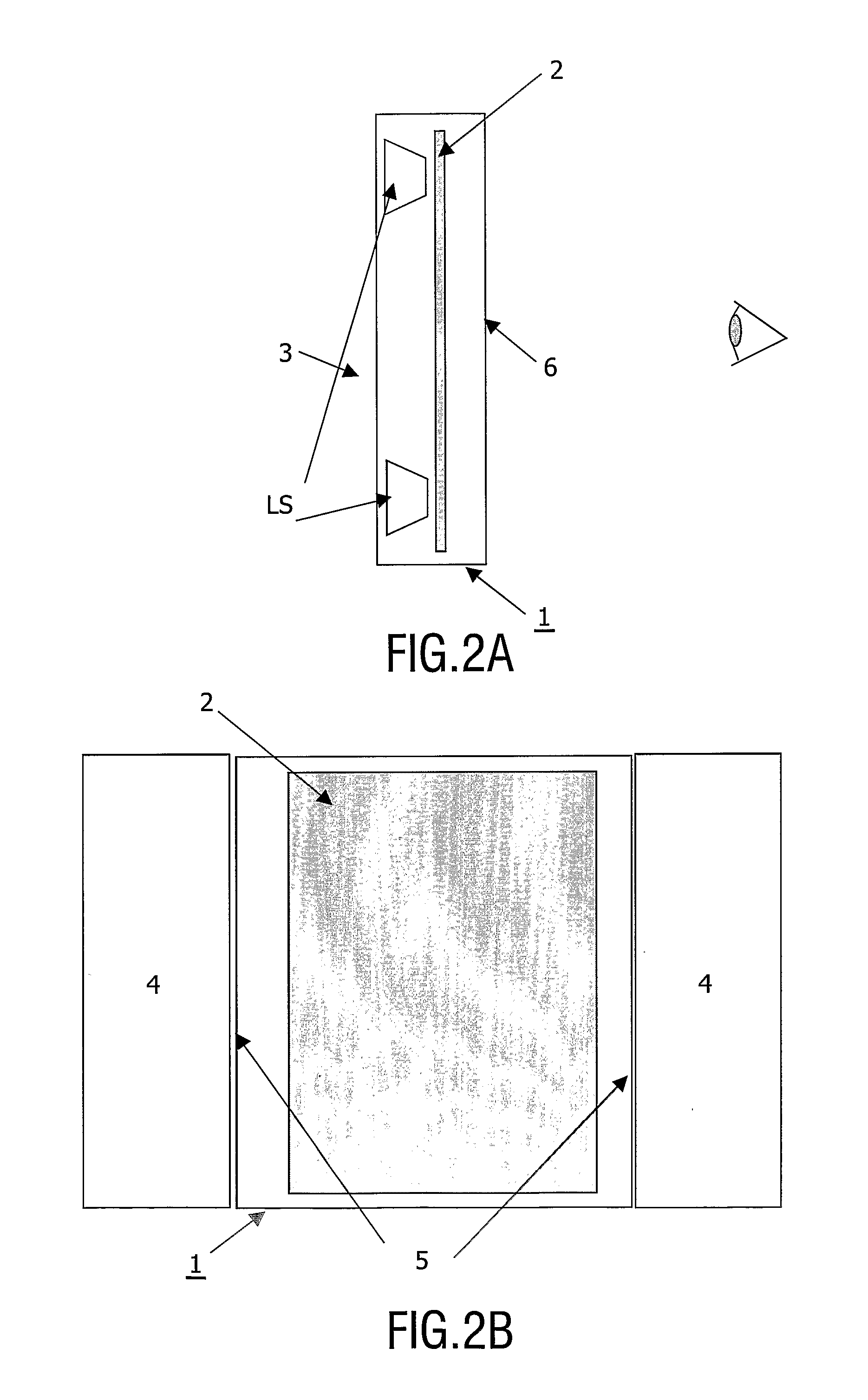
[0031]Such display devices are often provided with means for generating sound. Conventional loudspeakers are generally used to generate sound. Flat panel acoustic transducers are used in the device according to the invention. Such transducers offer advantages over conventional loudspeakers in that they are flat. FIG. 2A shows a configuration in which loudspeakers LS are provided behind the screen 2. However, holes then have to be provided so as to allow free air movement. These holes are undesirable.

[0032]It is known, for instance, from International Patent application WO 97 / 09854 to place panel acoustic transducers 4 next to the display panel in the form of rectangular flat panel loud...


PUM


Abstract

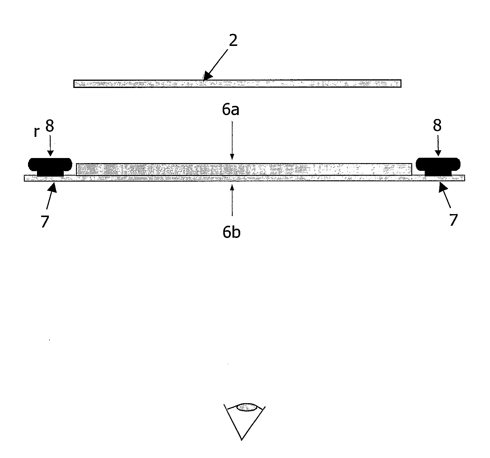
A display device (1) comprises a transparent panel acoustic transducer (6). The transparent front panel (6) has a laminate comprising an outer transparent thin panel (6b) and a supporting panel (6a). The supporting panel (6a) has a considerably larger stiffness than the transparent thin panel (6b), and the transparent thin panel (6b) comprises, at at least one side of the supporting panel, a side area (7) extending beyond the supporting panel (6a), said extending side area (7) being provided with an exciter (8) or a receiver at a side facing the display screen (2).

Description

FIELD OF THE INVENTION[0001]The invention relates to a display device comprising a panel acoustic transducer.[0002]Panel acoustic transducers are, for instance, panel speakers and panel microphones.[0003]Panel speakers are used for sound-generating devices, such as loudspeakers, and are often used as a part of another device such as a mobile telephone, radio, television, etc. Panel microphones are used to record sound.[0004]The invention also relates to a transparent panel acoustic transducer.BACKGROUND OF THE INVENTION[0005]The use of panel acoustic transducers offers the possibility of reducing the size and / or weight of a device in comparison with devices comprising standard loudspeakers, so that new designs become possible.[0006]It is known to place transducers behind the front panel. In devices in which the loudspeakers are behind the front panel, holes have to be provided in the panel so as to allow free air movement. These holes are undesirable.[0007]It is known, for instance,...

Claims


Application Information

Patent Timeline
Patent Type & Authority Applications(United States)
IPC IPC(8): H04R7/02H04R5/02H04R7/00
CPCH04R7/045H04R2499/15H04R23/00H04R7/10H04R7/02
Inventor WAGENAARS, WILHELMUS MARIAGOUWY, CHRISTIAAN MICHEL WILLYDEBELS, DIETER MARIE ROGERVAN DEN TILLAAR, JOHANNES HERMANUSDE PAUW, PETER GILBERT CLEMENTVAN BRUSSEL, HARRYLOEYS, GEERT JOSEPH MARIAVAN DEN THILLART, MART P.M.
Owner KONINKLIJKE PHILIPS ELECTRONICS NV
Learn More