
Multi-user touch screen

a multi-user, touch screen technology, applied in the direction of instruments, computing, electric digital data processing, etc., can solve the problems of only detecting a single touch, unable to distinguish or disambiguate two fingers placed on the surface at the same time, and a portion of the light to be refracted into the body of the user

Active Publication Date: 2008-04-17
DISNEY ENTERPRISES INC
View PDF35 Cites 135 Cited by
  • Summary
  • Abstract
  • Description
  • Claims
  • Application Information

AI Technical Summary

Benefits of technology

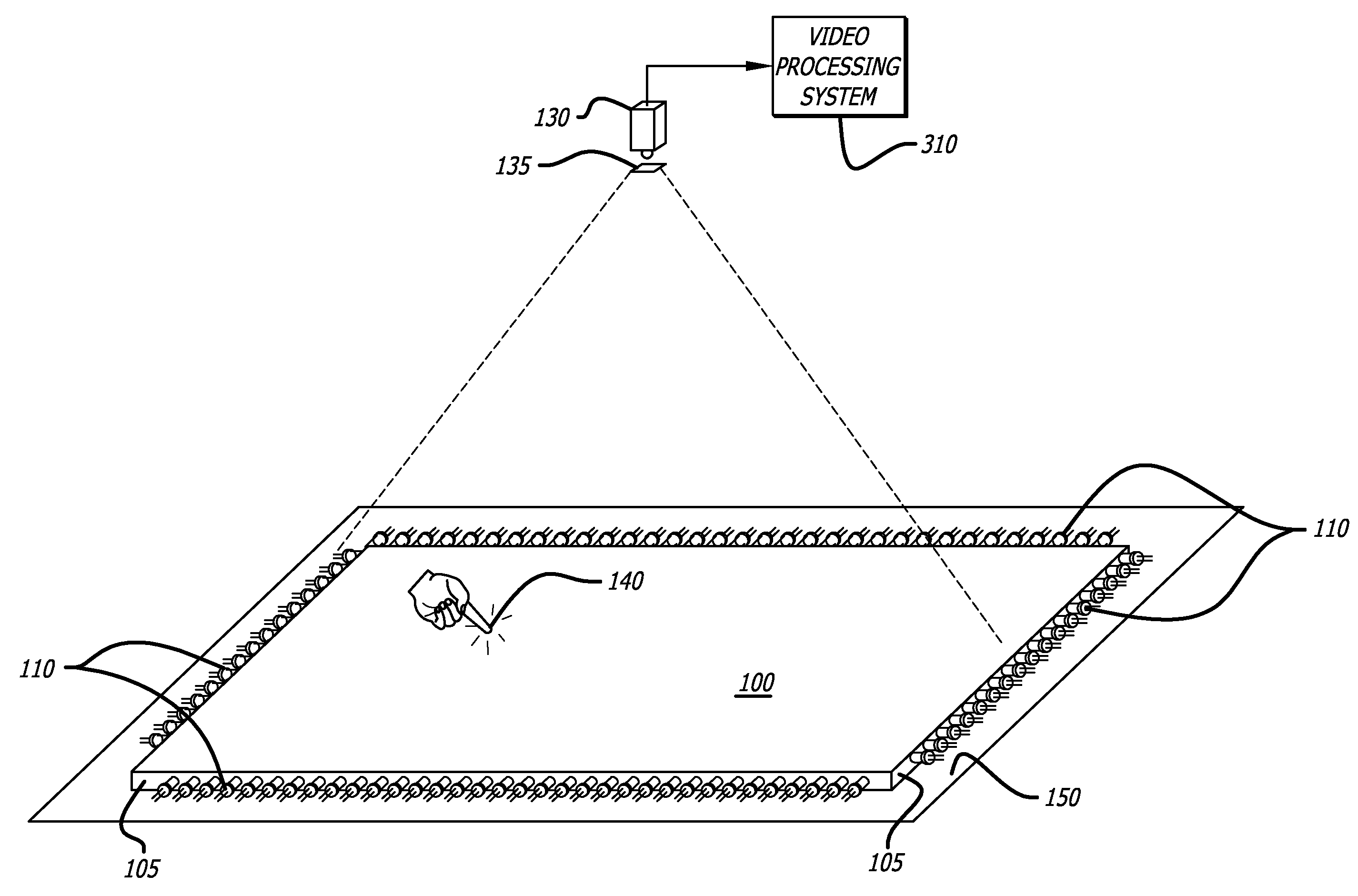
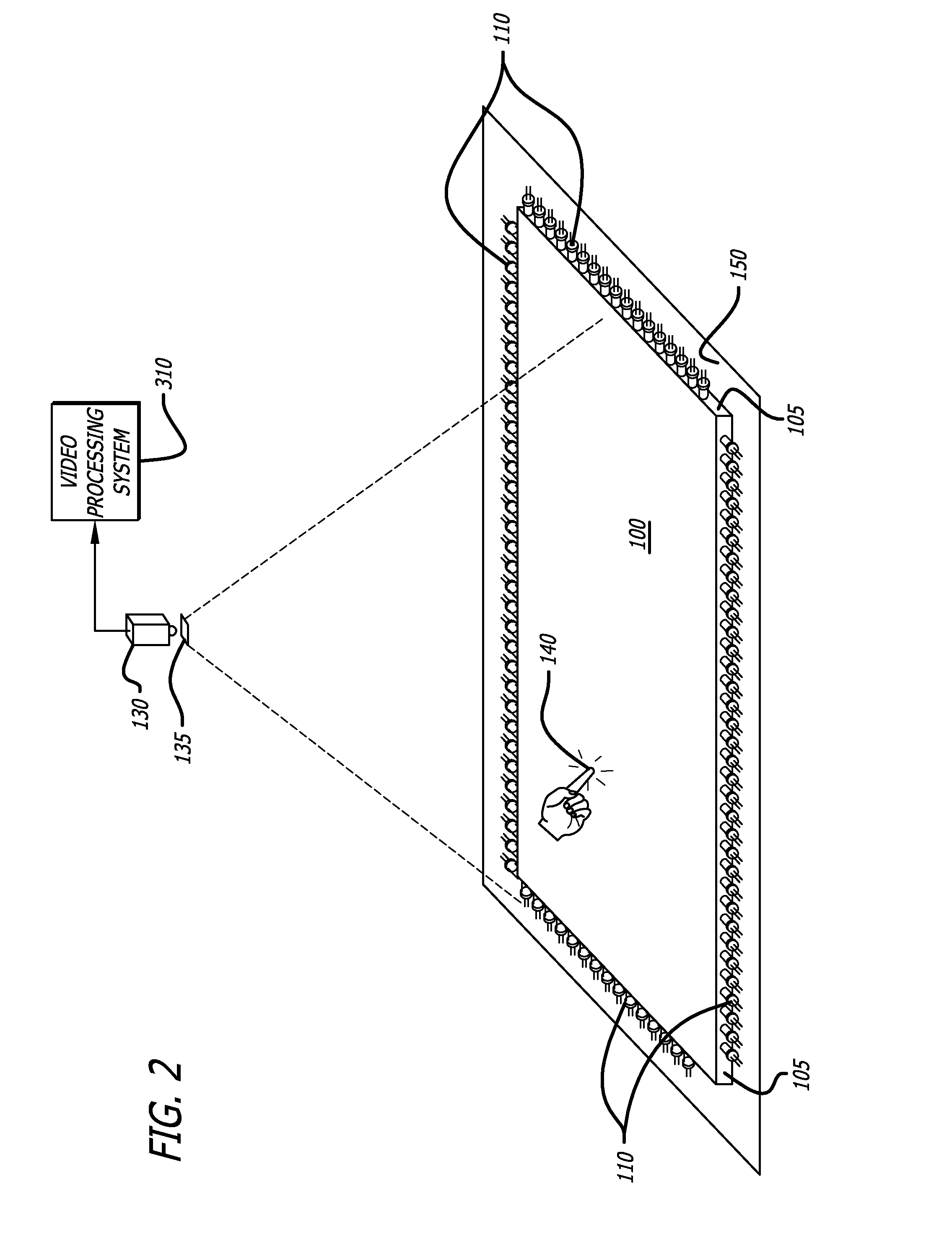
[0010]The touch-detection method and system can be combined with the projection of video information onto a translucent surface that is parallel to the touch screen. Furthermore, the translucent surface can be adjacent to the slab. Optical filters are used to prevent interference between the projected information and light used to detect touches.
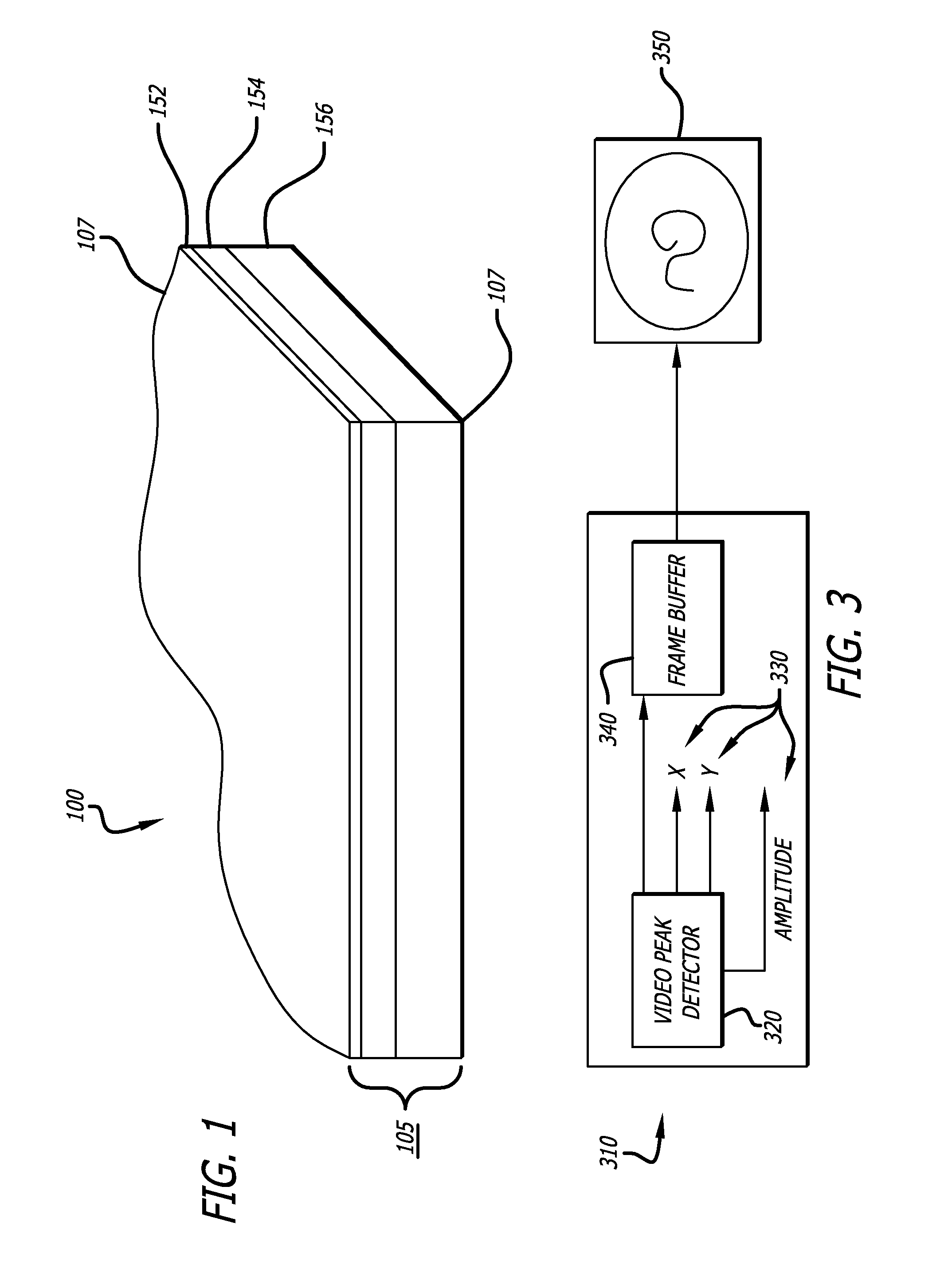
[0017]In one aspect, there is yet another method of detecting touch on a touch-screen surface. A transparent slab comprising a top surface and a bottom surface, and at least one side edge is provided. A transparent yielding sheet is applied on the top slab surface of the transparent slab, wherein the transparent yielding sheet has an index of refraction substantially similar to the index of refraction of the transparent slab, the transparent yielding sheet comprising a top sheet surface and a bottom sheet surface. Light is then injected into the transparent slab by placing at least one light source on the at least one side edge of the transparent slab. The at least one light source being placed so as to cause light injected into the transparent slab to be totally internally reflected in the transparent slab and transparent yielding sheet, so that the top sheet surface and the bottom slab surface emit a minimum amount of light. A pressing touch is received on the top sheet surface with a body part. The pressing touch causes a portion the transparent yielding sheet to deform to the shape of the pressing touch. The pressing touch disrupts the total internal reflection of a portion of the light thereby causing the portion of the light to be refracted into the body part. Finally, a camera captures the portion of the light refracted into the body part due to the pressing touch on the flexible sheet.

Problems solved by technology

Current systems can generally detect only a single touch, and cannot distinguish or disambiguate two fingers placed on the surface simultaneously.
The spot of light is created by a user touching the transparent slab with a body part, wherein the touch of the user on the transparent slab disrupts the total internal reflection of a portion of the light thereby causing the portion of the light to be refracted into the body part of the user.
The contact between the flexible diffusing sheet and the portion of the top surface of the transparent slab disrupts the total internal reflection of a portion of the light thereby causing the portion of the light to be refracted into the flexible diffusing sheet.
The pressing touch disrupts the total internal reflection of a portion of the light thereby causing the portion of the light to be refracted into the body part.

Method used


Image

  • Multi-user touch screen
  • Multi-user touch screen
  • Multi-user touch screen

Examples


Embodiment Construction

[0032]A touch-screen system and method is disclosed, where the light is trapped within a transparent slab with a higher index of refraction than the media surrounding the slab. The light is generally introduced at the edges of the slab. A portion of the light is captured within the slab since some of it is propagated at less than the critical angle to its surface so that the slab's inner surface acts as a loss-less mirror. This guided light remains substantially trapped within the slab until the light encounters an edge of the slab, or with an object with an index of refraction that is close to that of the slab. Such a matching interface can exist between the surface, and for instance, a human fingertip. At the point of contact with a fingertip, light from the slab leaks out of the slab and into the skin of the fingertip. This light is both reflectively scattered, and diffusely transmitted, by the amorphous skin tissue of the finger-tip, and can be viewed from the side of the slab o...


PUM


Abstract

A multi-user touch-responsive viewing screen is described which uses frustrated total internal reflection in a slab of transparent material to illuminate the contact point between the slab and a finger or other object substantially matching the slab's index of refraction. Light, coupled upon touch, can be detected with a video camera, and used to determine both the position and pressure of the touch. Multiple touches can be accommodated and each touch accurately located. Projected images can be applied to the slab and a diffuser to construct an interactive touch screen.

Description

BACKGROUND OF THE DISCLOSURE[0001]1. Field of the Disclosure[0002]The present disclosure relates to interactive projection systems. In particular, it relates to entertainment projection systems to provide an illusory reality to the observer.[0003]2. General Background[0004]Current touch screen systems permit companies to provide their customers the ability to instruct interactive systems by simply touching a surface. Examples are the touch-screens often mounted on computer displays, or the various touch screens used to indicate pointing in connection with automatic teller machines, industrial controllers, entertainment, transportation, etc.[0005]Various X-Y position measurement systems are typically used to determine the position of a finger, or a stylus on their surface. For instance, in resistive type touch-pads the position of a finger provides the “wiper” location in a voltage dividing potentiometer. The divider is formed by a resistive membrane that is shorted to a conductive l...

Claims


Application Information

Patent Timeline
Patent Type & Authority Applications(United States)
IPC IPC(8): G06F3/041
CPCG06F2203/04109G06F3/0425
Inventor SMOOT, LANNY STARKES
Owner DISNEY ENTERPRISES INC
Learn More