Installation light

a technology for installing lights and light fixtures, which is applied in the direction of vehicle lighting systems, light fastenings, lighting and heating apparatuses, etc. it can solve the problems of heavy installation lights, difficult to operate installation lights by passengers with limited tactile capabilities, and easy wear and maintenance. , to achieve the effect of simple operation and low wear and maintenan

Inactive Publication Date: 2008-04-17
BE AEROSPACE SYST
View PDF8 Cites 32 Cited by
  • Summary
  • Abstract
  • Description
  • Claims
  • Application Information

AI Technical Summary

Benefits of technology

[0008]Against this background, it is the object of the invention to provide an installation light which is low in wear and maintenance, which is simple to operate and meets today's high standards of design appearance.

Problems solved by technology

The movable components which are required for this, render the installation lights heavy, prone to wear and expensive in maintenance.
Apart from this, it has been found that these installation lights are difficult to operate by passengers with limited tactile capabilities.
The application of such an illumination device in passenger cabins of aircraft, buses and trains, with which the lighting devices are arranged above the seat locations, tends to be rather disadvantageous, since there it is possible to leave the seating locations and this, with the movements of the passengers which this entails, may change the emittance characteristics of these illumination devices in an unintended manner.
Inasmuch as this is concerned, the lighting devices described in DE 10 2004 039 284 A1 also tend to be rather unsuitable for the application as a reading light in passenger cabins of aircraft, buses and trains.

Method used


Image

  • Installation light
  • Installation light

Examples


Embodiment Construction

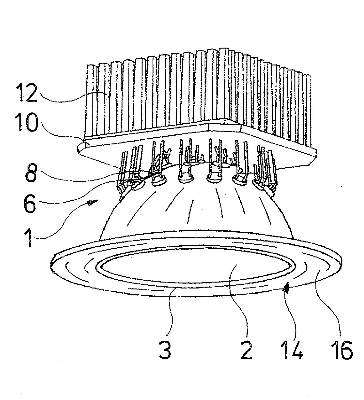
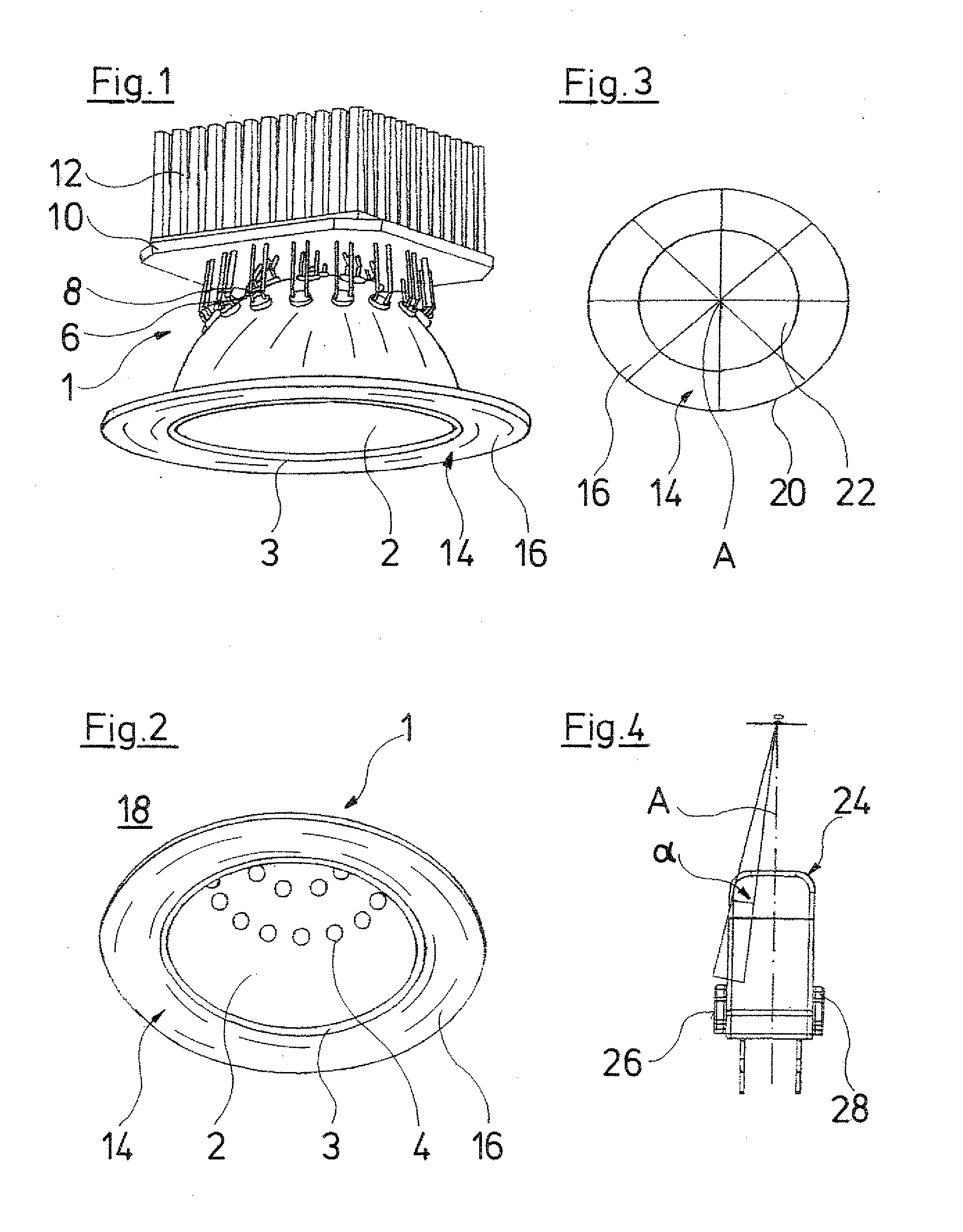
[0030]Referring to the drawings in particular FIGS. 1 and 2 show a vehicle installation light and aircraft installation light 1 with a reflector 2 curved in a spherically concave manner, in the shape of a hemispherical shell. A circular cover disk 3 of a transparent, i.e. light-permeable material is arranged on the end-side of this hemispherical shell, and this disk closes the inner space of the reflector 2.

[0031]A multitude of light emitting diodes 4, which form the lighting means of the installation light 1, is arranged in the region of the spherical cap of the hemispherical shell, in the reflector 2. Adjacent light emitting diodes 4 here in each case have the same distance to one another. The alignment of the light emitting diodes 4 is such that the main emittance direction of the light emitting diodes corresponds essentially to the radius of curvature of the reflector 2 at the location of its arrangement on the reflector 2. In this manner, each light emitting diode 4 has an emit...


PUM


Abstract

An installation light for a vehicle or aircraft comprises a multitude of lighting elements. These lighting elements may be activated individually or in groups, in a manner such that the radiation direction and/or emittance angle of the light emitted by the installation light may be adjusted.

Description

CROSS REFERENCE TO RELATED APPLICATIONS[0001]This application claims the benefit of priority under 35 U.S.C. § 119 of German Patent Application DE 10 2006 048 711.7 filed Oct. 14, 2006, the entire contents of which are incorporated herein by reference.FIELD OF THE INVENTION[0002]The present invention relates to an installation light and more particularly relates to a vehicle installation light or aircraft installation light with a multitude of lighting elements, which individually or in groups, may be activated in a manner such that the beam direction and / or the emittance angle (α) of the light emitted by the installation light may be adjusted.BACKGROUND OF THE INVENTION[0003]It is usual to provide installation lights in passenger cabins of aircraft, buses, trains and likewise, above the passenger seats, these installation lights in each case being assigned to a seat. These installation lights, as a rule, are designed such that their emittance angle, i.e. the spatial angle of the li...

Claims


Application Information

Patent Timeline
Patent Type & Authority Applications(United States)
IPC IPC(8): B64D47/02F21W106/00F21W107/00F21W107/30
CPCB60Q3/0253B60Q3/0259B60Q3/0296F21Y2101/02F21S8/02F21V23/0442F21W2101/08B64D2011/0053B60Q3/44B60Q3/47B60Q3/82F21V23/0485F21Y2115/10F21W2106/00
Inventor GUNNEWIG, FRANKGOKE, RALFMARQUARDT, WOLFGANGFOLLET, CHRISTOPHER
Owner BE AEROSPACE SYST
Why Eureka
Try Eureka