Deairing type hydraulic tensioner

Inactive Publication Date: 2008-04-17
TSUBAKIMOTO CHAIN CO
View PDF8 Cites 28 Cited by
  • Summary
  • Abstract
  • Description
  • Claims
  • Application Information

AI Technical Summary

Benefits of technology

[0012]The ball spring disposed in the hollow flow passage of the ball seat, biases the check ball valve toward its opened condition, and more effectively and

Problems solved by technology

In the conventional hydraulic tensioner 500 shown in FIG. 6, the check valve assembly 540 can block reverse flow of oil from the high pressure oil chamber R. However, air can become mixed with the oil in the high pressure oil chamber R. Since air is compressible, the presence of air, in the high pressure oil chamber impairs the damping action of the tensioner.
Consequently noise can be generated by backlash in the timing chain upon starting of the en

Method used


Image

  • Deairing type hydraulic tensioner
  • Deairing type hydraulic tensioner
  • Deairing type hydraulic tensioner

Examples


Example

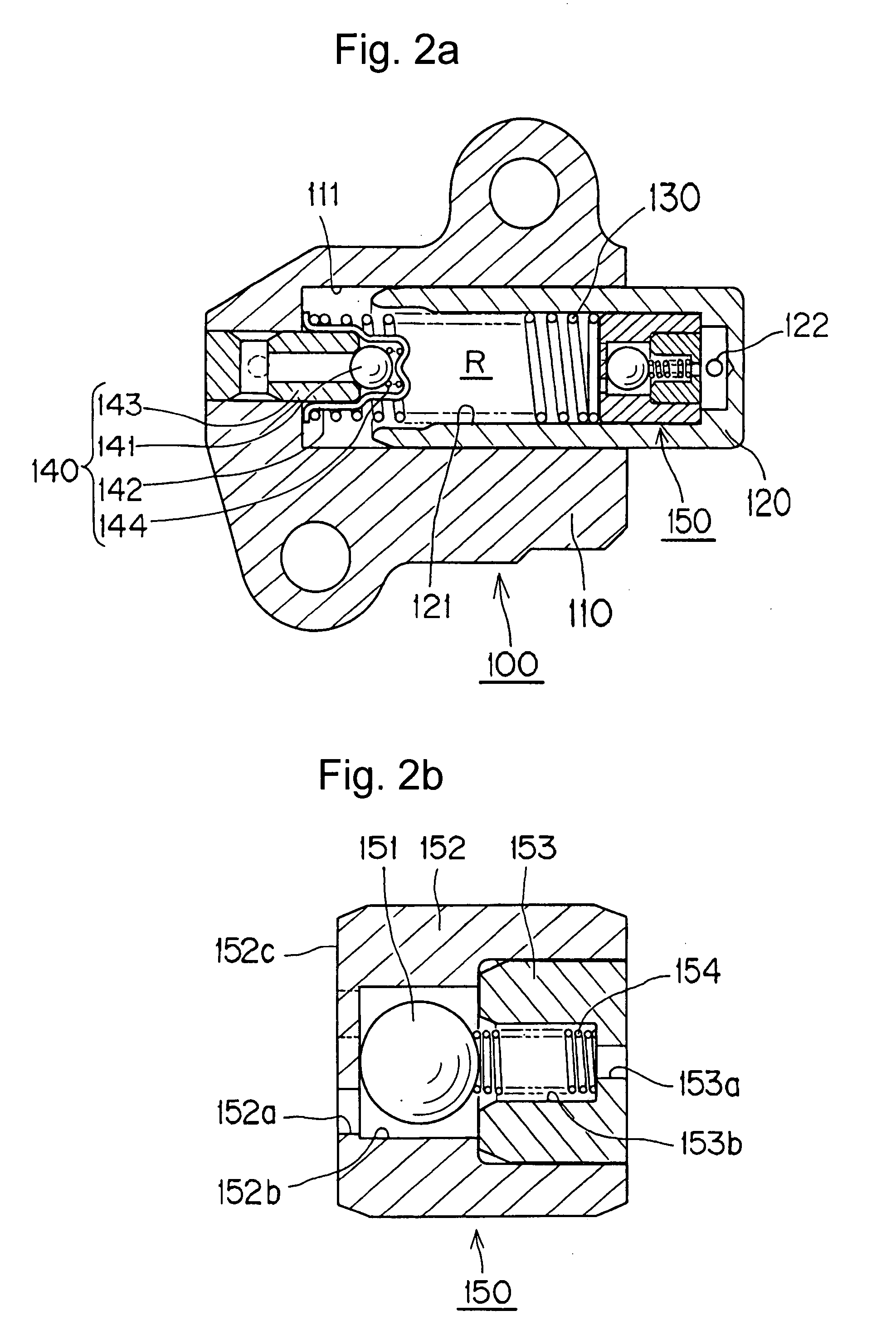
[0024]The deairing check valve according to the invention, in which the check ball is spring-biased away from its seat toward the high pressure oil chamber, can be incorporated into the plunger or body of any of various kinds of hydraulic tensioners, including hydraulic tensioners having ratchet mechanisms.

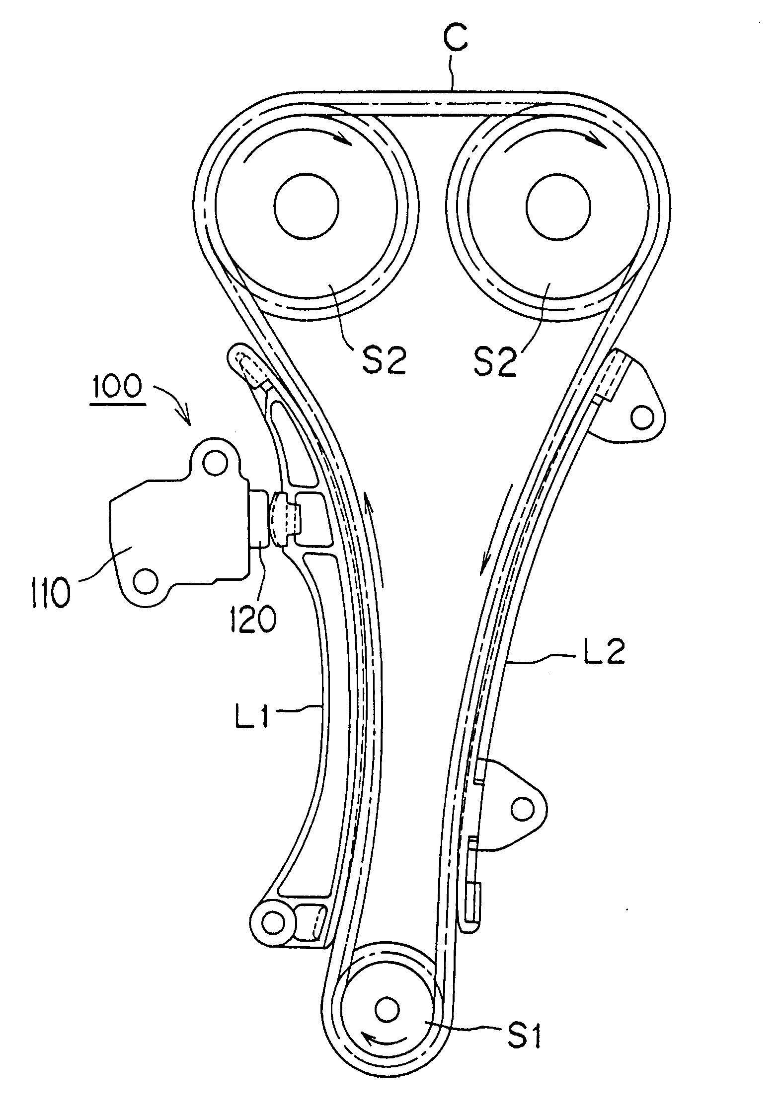
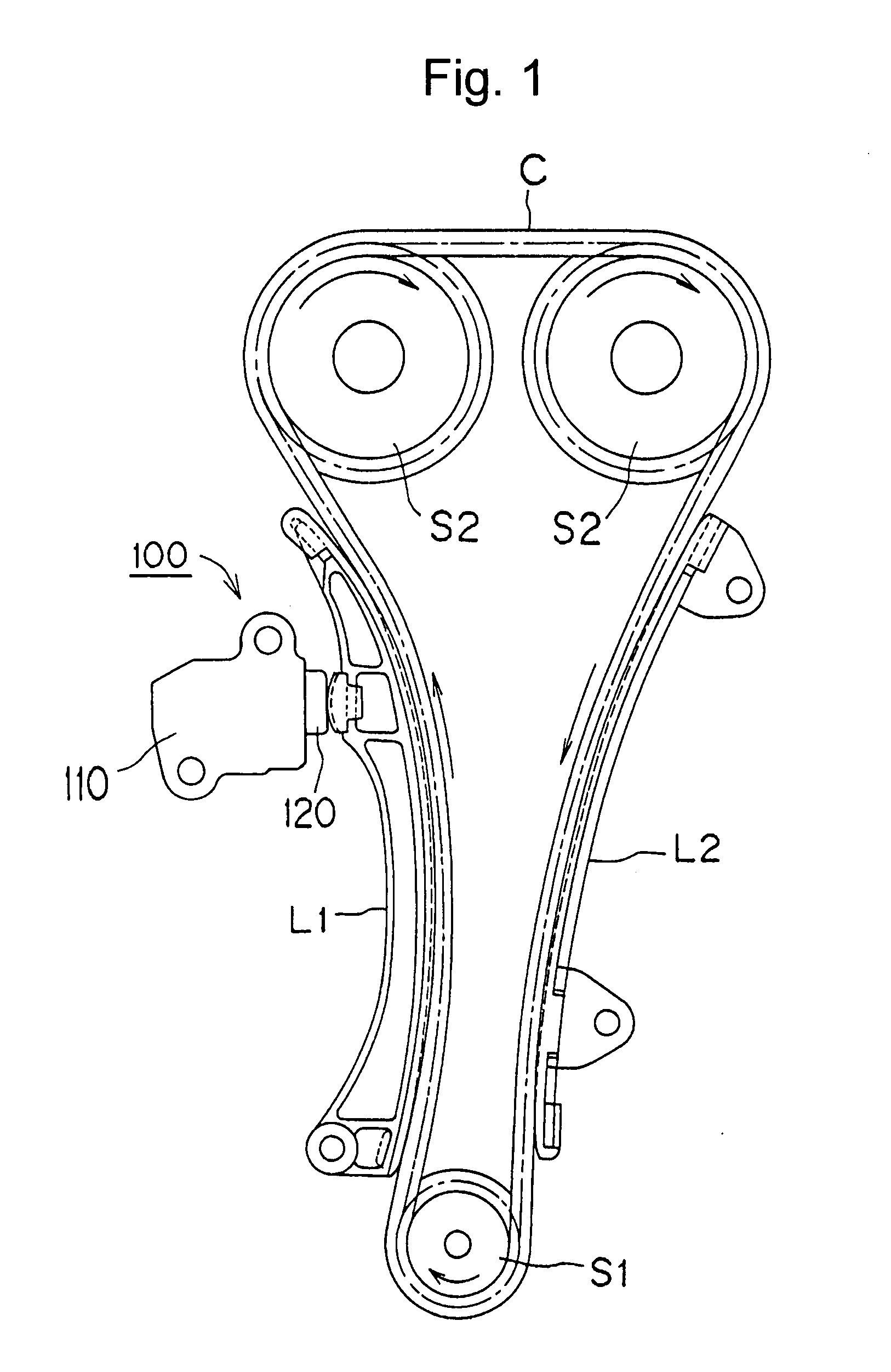
[0025]The deairing type hydraulic tensioner 100, shown in FIG. 1, is attached to an engine body adjacent the slack side of a timing chain C, arranged to transmit power from a driving sprocket S1 rotated by an engine crankshaft to a pair of driven sprockets S2 on the engine camshafts. A plunger 120 protrudes from the tensioner body 110 and engages a pivoted lever L1 on which the slack side of the chain slides. The plunger engages the lever at a location remote from the lever's pivot, causing the lever to press against the chain so that the lever applies tension to the chain. A fixed guide L2, which is also attached to an engine body, is in sliding engagement with the tension side o...


PUM


Abstract

In a hydraulic tensioner comprising a tensioner body and a hollow plunger slidable in a plunger-receiving hole, a deairing check ball assembly comprises a check ball, a ball seat, a ball retainer and a check ball biasing spring arranged to bias the check ball away from the seat and toward a high pressure chamber formed by a plunger-receiving hole and the interior of the plunger. The deairing check ball assembly can be incorporated into the tensioner body or into the plunger.

Description

[0001]This application claims priority on the basis of Japanese patent application 2006-278985 filed Oct. 12, 2006. The disclosure of Japanese application 2006-278985 is hereby incorporated by reference.FIELD OF THE INVENTION[0002]This invention relates to a hydraulic tensioner for applying proper tension to a timing belt, a timing chain, or the like, in a vehicle engine.BACKGROUND OF THE INVENTION[0003]A hydraulic tensioner including a ball-type check valve for blocking reverse flow of oil from the high pressure oil chamber of the tensioner has been widely used for maintaining proper tension in the timing belt or timing chain used to transmits rotation from the crankshaft to one or more camshafts in a vehicle engine.[0004]A typical hydraulic tensioner 500, as shown in FIG. 6, includes a hollow, cylindrical, plunger 520, slidably protruding from a hole 511 formed in a body 510, a plunger biasing spring 530, in compression between the end wall of the hole 511 a front end wall of a ho...

Claims


Application Information

Patent Timeline
IPC IPC(8): F16H7/08
CPCF16H7/0836F16H7/0848F16H2007/0859F16H2007/0817F16H2007/0806F16H7/08
Inventor NAMIE, TSUTOMUHASHIMOTO, HIROSHI
Owner TSUBAKIMOTO CHAIN CO
Why Eureka
Try Eureka