Steerable catheter using flat pull wires and having torque transfer layer made of braided flat wires

a technology of flat pull wires and torque transfer layers, which is applied in the field of catheters, can solve the problems of relatively large distances of steering force transmission, and the thin-walled introducer is more likely to collapse upon itself, so as to achieve greater flexibility, greater flexibility and control of the catheter, and reduced overall cross-section of the catheter

Inactive Publication Date: 2008-04-17
ST JUDE MEDICAL ATRIAL FIBRILLATION DIV
View PDF16 Cites 225 Cited by
  • Summary
  • Abstract
  • Description
  • Claims
  • Application Information

AI Technical Summary

Benefits of technology

[0023] A technical advantage of the present invention is that overall cross-section of the catheter may be reduced.
[0024] Another technical advantage of the present invention is that a steerable catheter using flat pull wires may be provided that enjoys greater flexibility.
[0025] Yet another technical advantage of the invention is it may utilize an improved braided wire assembly that provides for greater flexibility and control of a catheter.
[0026] A further technical advantage of the invention is that a method of manufacturing an improved steerable catheter is provided.
[0027] Yet another technical advantage of the invention is that a catheter shaft having greater flexibility and control may be utilized.
[0028] A further technical advantage of the invention is that a method of manufacturing an introducer with a lower profile outer diameter with improved steerability is provided.

Problems solved by technology

Furthermore, since the path within the patient is often long and tortuous, steering forces must be transmitted over relatively great distances.
A thin-walled introducer, however, is more likely to collapse upon itself when a torque is applied at its proximal end.

Method used


Image

  • Steerable catheter using flat pull wires and having torque transfer layer made of braided flat wires
  • Steerable catheter using flat pull wires and having torque transfer layer made of braided flat wires
  • Steerable catheter using flat pull wires and having torque transfer layer made of braided flat wires

Examples


Embodiment Construction

[0048] Flat Pull Wires

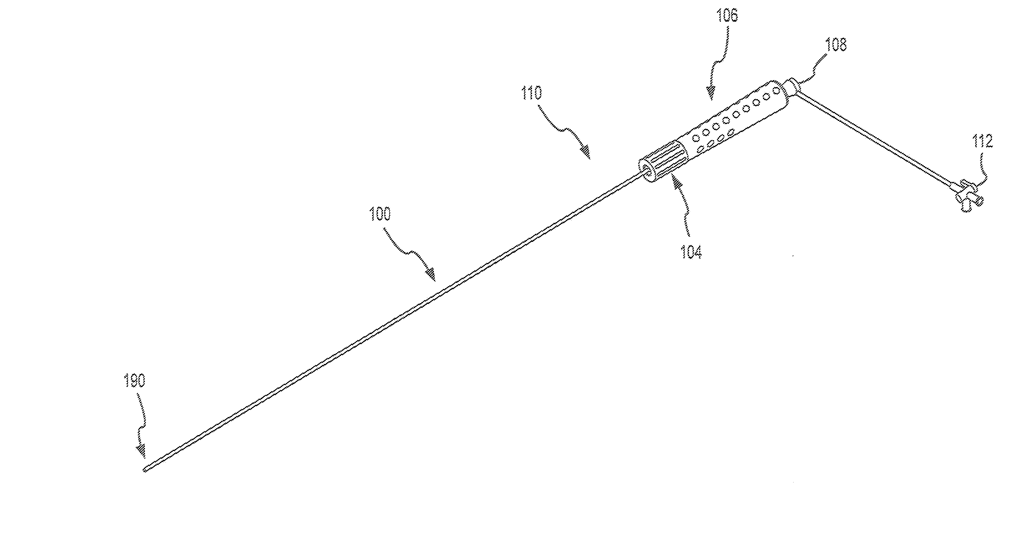
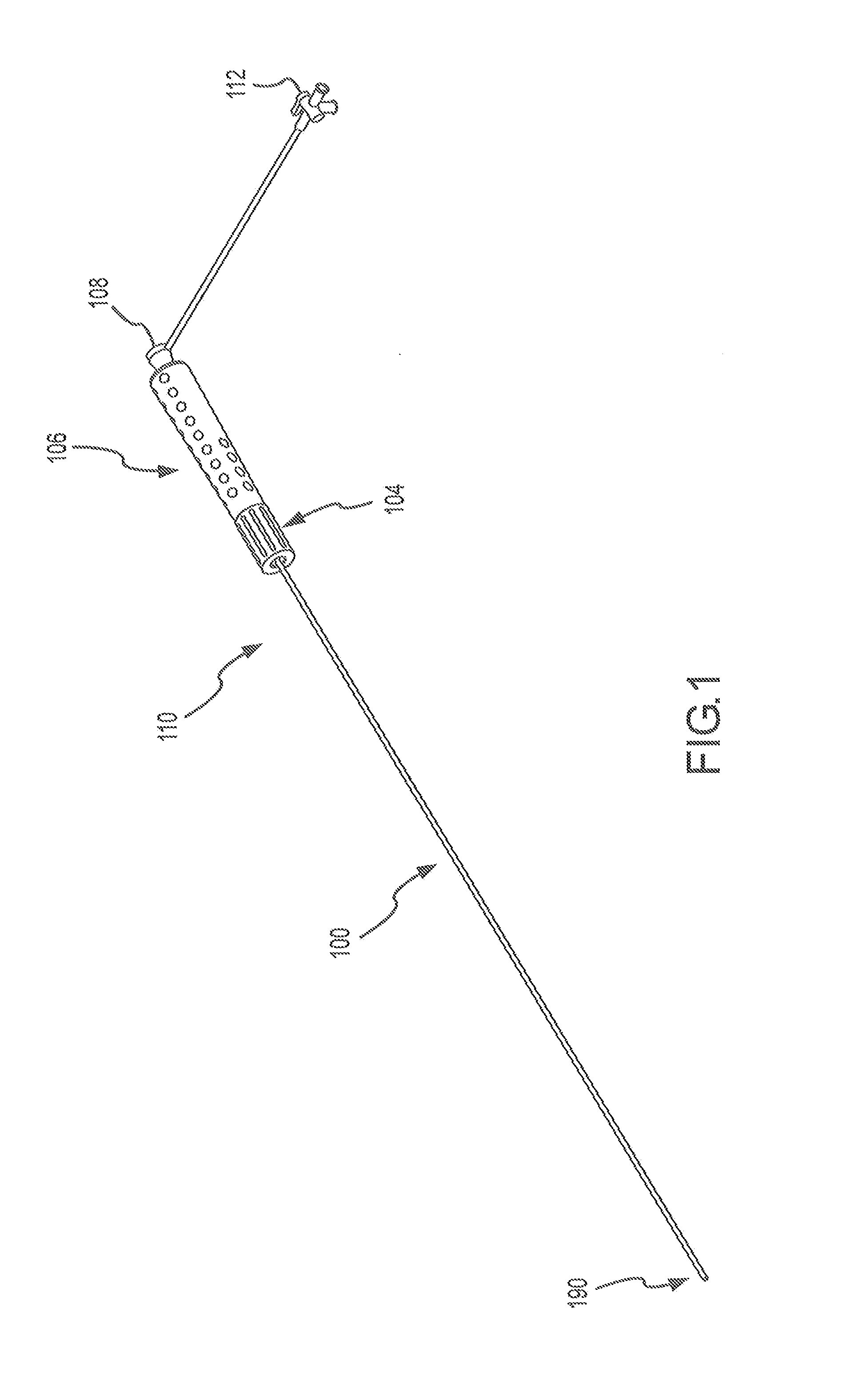
[0049] The present invention provides an improved steerable catheter that minimizes the overall outer dimensions by utilizing a variety of improved techniques. One technique is to utilize flat wire as the pull wires for the steerable catheter.

[0050] For purposes of this invention, a “flat wire” or a “flat pull wire” refers to a wire that is characterized by a cross-section that, when measured along two orthogonal axes, is substantially flat. A flat wire typically has a rectangular cross-section. For example, the rectangular cross-section may be approximately 0.004″×0.012″. The cross-section need not be perfectly rectangular. For example, the present invention contemplates a cross-section of the flat wire may be oval, provided that the overall cross-section is generally flat. For example, a wire may be properly characterized as a flat wire if it has a cross-section that is measured X in one direction and at least 3X in a second direction generally orthogonal t...


PUM

PropertyMeasurementUnit
depthaaaaaaaaaa
depthaaaaaaaaaa
depthaaaaaaaaaa

Abstract

A catheter assembly includes an inner liner made of flexible material and an outer layer having a steering mechanism. The steering mechanism includes at least one flat wire and a corresponding lumen through which the flat wire may travel. The steering mechanism may also include at least one pull ring to which the flat wires are attached. A layer of heat shrink material may encompass the outer layer. A braided wire assembly may also be provided in the outer layer, and may be formed by braiding a plurality of flat wires into a wire mesh. The overall cross-section of the catheter assembly is preferably substantially circular. A catheter shaft may include a plurality of segments of differing hardness characteristics. The outer layer typically comprises a melt processing polymer such that the catheter assembly may be laminated using heat.

Description

CROSS-REFERENCE TO RELATED APPLICATIONS [0001] This application is a continuation-in-part of U.S. patent application Ser. No. 11 / 647,313, filed 29 Dec. 2006, which claims the benefit of U.S. Provisional Patent Application No. 60 / 800,373, filed 16 May 2006. The entire disclosures of these applications are hereby expressly incorporated by reference as though fully set forth herein.BACKGROUND OF THE INVENTION [0002] a. Field of the Invention [0003] The present invention pertains generally to catheters that are used in the human body. More particularly, the present invention is directed to steerable catheters using flat pull wires to reduce the overall outer dimension of the catheter and a torque transfer layer made of braided flat wires and configured to provide increased strength, flexibility, and kink resistance. [0004] b. Background Art [0005] Catheters are used for an ever-growing number of procedures. For example, catheters are used for diagnostic, therapeutic, and ablative proced...

Claims


Application Information

Patent Timeline
Patent Type & Authority Applications(United States)
IPC IPC(8): A61M25/01
CPCA61M25/0012A61M25/0045A61M25/01A61M25/0147A61M2025/015A61M25/0053
Inventor HEIDEMAN, WAYNEFUENTES, ALLAN M.STEHR, RICHARD E.CUMMING, SARAHDUSTRUDE, MARK
Owner ST JUDE MEDICAL ATRIAL FIBRILLATION DIV
Why Eureka
Try Eureka