
Data Management System, Data Management Method, Server Apparatus, Receiving Apparatus, Control Program, and Computer-Readable Recording Medium Recording Same

Inactive Publication Date: 2008-04-17
SHARP KK
View PDF11 Cites 7 Cited by
  • Summary
  • Abstract
  • Description
  • Claims
  • Application Information

AI Technical Summary

Benefits of technology

[0015] With this, when a new version of a file group is downloaded into a receiving apparatus in which an older version of the file group is stored, a data file which constitutes the older version of the file group and which is replaced by a data file constituting the new version of the file group can be deleted for example. Therefore, the data file which constitutes the older version of the file group can be prevented from being wrongly used.
[0017] As described above, according to the foregoing arrangement, in a data management system in which a server apparatus storing a plurality of data files appropriately delivers the plurality of data files to a receiving apparatus, data management in the receiving apparatus can be effectively performed.
[0023] With this, when a new version of a file group is downloaded into a receiving apparatus in which an older version of the file group is stored, a data file which constitutes the older version of the file group and which is replaced by a data file constituting the new version of the file group can be deleted for example. Therefore, the data file which constitutes the older version of the file group can be prevented from being wrongly used.
[0025] As described above, according to the foregoing arrangement, in a data management system in which a server apparatus storing a plurality of data files appropriately delivers the plurality of data files to a receiving apparatus, data management in the receiving apparatus can be effectively performed.

Problems solved by technology

This causes such a problem that reproduction different from that originally expected is performed by referring to another file that was downloaded in the past.

Method used


Image

  • Data Management System, Data Management Method, Server Apparatus, Receiving Apparatus, Control Program, and Computer-Readable Recording Medium Recording Same
  • Data Management System, Data Management Method, Server Apparatus, Receiving Apparatus, Control Program, and Computer-Readable Recording Medium Recording Same
  • Data Management System, Data Management Method, Server Apparatus, Receiving Apparatus, Control Program, and Computer-Readable Recording Medium Recording Same

Examples


embodiment 1

[0050] An embodiment of the present invention will be described below with reference to FIGS. 1 through 6 and FIG. 15.

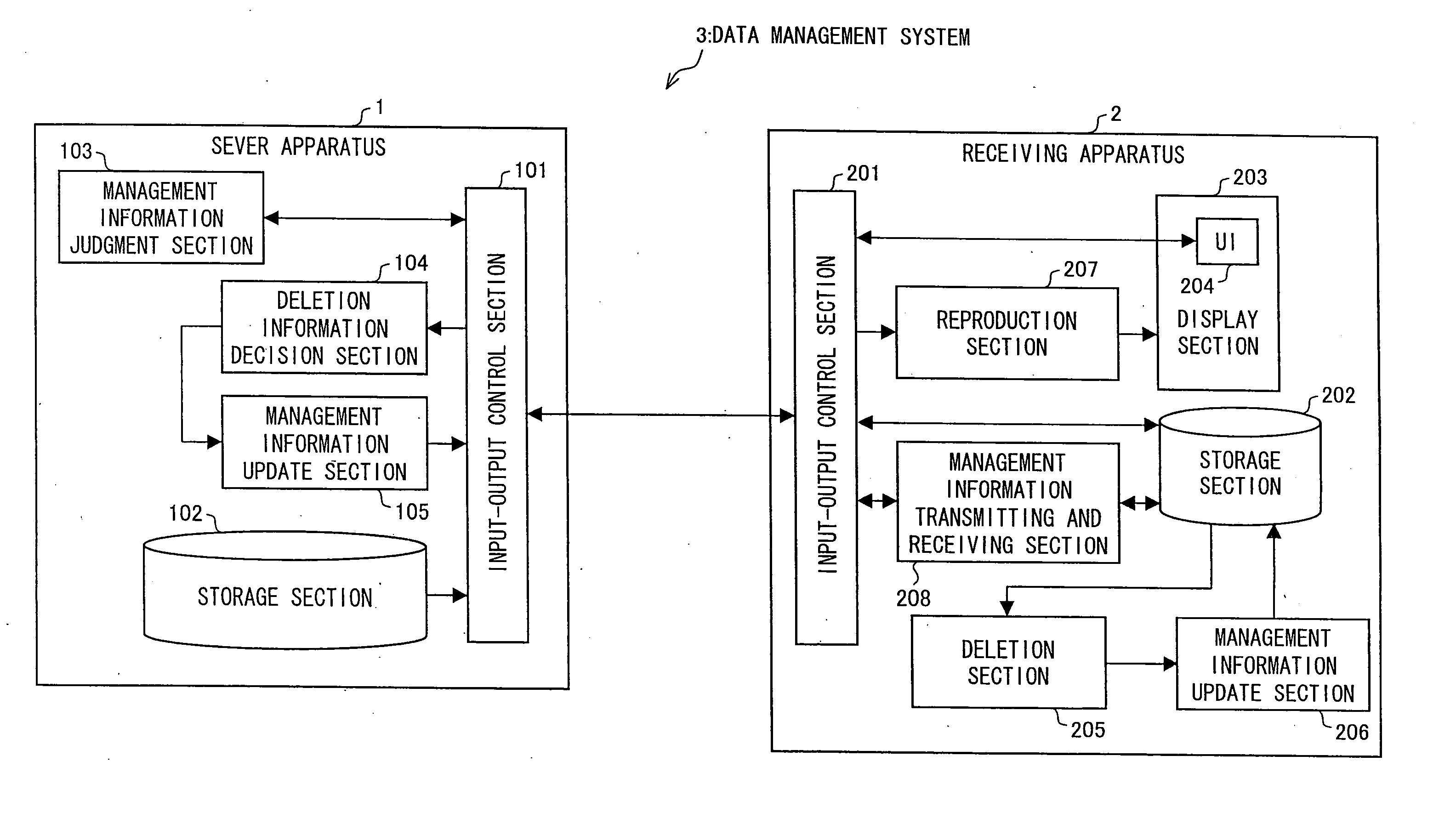
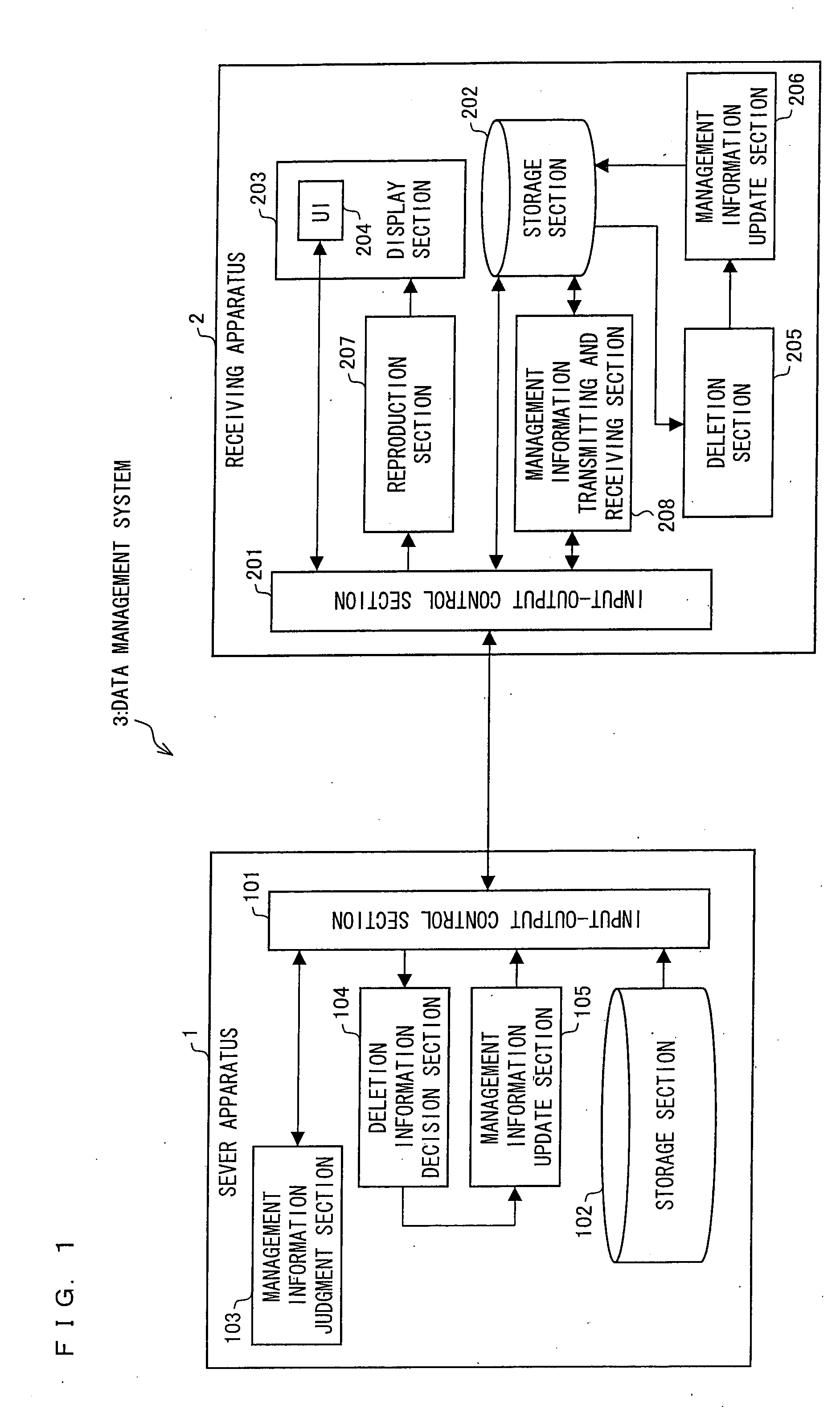
[0051]FIG. 1 is a functional block diagram showing a data management system 3 according to Embodiment 1 of the present invention.

[0052] The data management system 3 includes: a server apparatus 1, which stores and sends out a large number of AV contents; and a receiving apparatus 2, which receives, stores, and reproduces an AV content sent from the server apparatus 1.

[0053] The server apparatus 1 includes an input-output control section 101, a storage section 102, a management information judgment section 103, a delete information decision section 104, and a management information update section 105. Further, the receiving apparatus 2 includes an input-output control section 201, a storage section 202, a display section 203, a UI (user interface) 204 (included in the display section 203), a deletion section 205, a management information update section 206, a repro...

embodiment 2

[0107] Another embodiment of the present invention will be described below with reference to FIGS. 7 through 10. For convenience of explanation, components having the same functions as those described in Embodiment 1 are given the same referential marks, and will not be explained. Further, unless otherwise noted, the terms whose definitions are given in Embodiment 1 are used on the basis of the same definitions in the present embodiment.

[0108]FIG. 7 is a functional block diagram showing a structure of a data management system 3′ according to Embodiment 2. The structure of the data management system 3′ is about the same as that of the data management system 3 (see FIG. 1) of Embodiment 1; therefore, only the difference is explained. Note that the data management system 3′ includes a storage section 202′, a file management section 205′, and a reproduction section 207′ instead of the storage section 202, the deletion section 205, and the reproduction section 207.

[0109] In the data ma...

embodiment 3

[0133] Another embodiment of the present invention will be described below with reference to FIGS. 11 through 13. For convenience of explanation, components having the same functions as those described in Embodiments 1 and 2 are given the same referential marks, and will not be explained. Further, unless otherwise noted, the terms whose definitions are given in Embodiments 1 and 2 are used on the basis of the same definitions in the present embodiment.

[0134] In the data management systems 3 and 3′ (see FIGS. 1 and 7) according to Embodiments 1 and 2 described above, the server apparatus 1 carries out an update of management information for managing a file in the receiving apparatuses 2 and 2′. On the other hand, in a data management system 30 according to Embodiment 3, a receiving apparatus 20 carries out an update of management information entirely.

[0135]FIG. 11 is a functional block diagram showing a structure of a data management system 30 according to Embodiment 3 of the prese...


PUM


Abstract

A server device (1) includes a deletion information decision unit (104) for deciding a file to be deleted to prevent its use in a reception device (2) in the state that a file constituting an AV content to be transmitted is stored in an accumulation unit (202) among files

Description

TECHNICAL FIELD [0001] The present invention relates to (i) a data management system including (a) a server apparatus having a function of storing a plurality of data files and of appropriately delivering the plurality of data files to a receiving apparatus and (b) a receiving apparatus having a function of receiving a data file from the server apparatus and of storing the data file, (ii) a server apparatus and a receiving apparatus together constituting the data management system, (iii) a data management method, (iv) a control program, and (v) a computer-readable recording medium in which the control program is recorded. BACKGROUND ART [0002] Such a data service has been widely provided that servers and clients linked to one another via a network communicate with one another and that contents stored in server apparatuses are download into client terminals (receiving apparatuses) and used. Especially, because of the current widespread use of broadband networks, such a mechanism is b...

Claims


Application Information

Patent Timeline
IPC IPC(8): G06F17/30G06F13/00H04N7/173H04N21/258H04N21/4335H04N21/6332
CPCG06F17/30017H04L67/06Y10S707/99938Y10S707/99942Y10S707/99934G06F16/40G06F13/00G06Q50/10
Inventor WATANABE, SHUICHIKIYAMA, JIRO
Owner SHARP KK
Learn More