System and method for recording management data for management of solid-state electronic image sensing device, and system and method for sensing management data

Inactive Publication Date: 2007-11-06
FUJIFILM CORP
View PDF9 Cites 2 Cited by
  • Summary
  • Abstract
  • Description
  • Claims
  • Application Information

AI Technical Summary

Benefits of technology

[0008]Accordingly, an object of the present invention is to make it possible to read management data comparatively simply even when a solid-state electronic image sensing device is mounted on a circuit board or heat sink, etc., in intimate contact therewith.
[0019]Recording a plurality of the same items of management data makes it possible to prevent errors in reading the management data.
[0025]Preferably, a target image which has a uniform pattern and which is illuminated by an optically flat light source is sensed. This makes it relatively easy to extract management data from subject image data output by the solid-state electronic image sensing device.
[0034]An arrangement may be adopted in which the management data is recorded on the cover by at least one of an OCR (Optical Character Reader) font and a bar code. This raises the recognition rate of the management data.
[0038]A management-data check code may be recorded. This will make it possible to check the read management data for errors.
[0040]The management data preferably is recorded on an area of the cover with the exception of an area that is for forming an image on the light-receiving area. Thus it is possible to prevent the management data from appearing in the imaging area. This is particularly effective when irradiation is performed using invisible light of a high level to read the management data.

Problems solved by technology

When the management data is recorded on the back side of the solid-state electronic image sensing device, however, the data is difficult to read after the solid-state electronic image sensing device is mounted.
Since the management data is difficult to read, fault analysis of the solid-state electronic image sensing device and control of it, such as changing the applied voltage, also are difficult because the management data is used for such purposes.

Method used


Image

  • System and method for recording management data for management of solid-state electronic image sensing device, and system and method for sensing management data
  • System and method for recording management data for management of solid-state electronic image sensing device, and system and method for sensing management data
  • System and method for recording management data for management of solid-state electronic image sensing device, and system and method for sensing management data

Examples


first embodiment

(1) First Embodiment

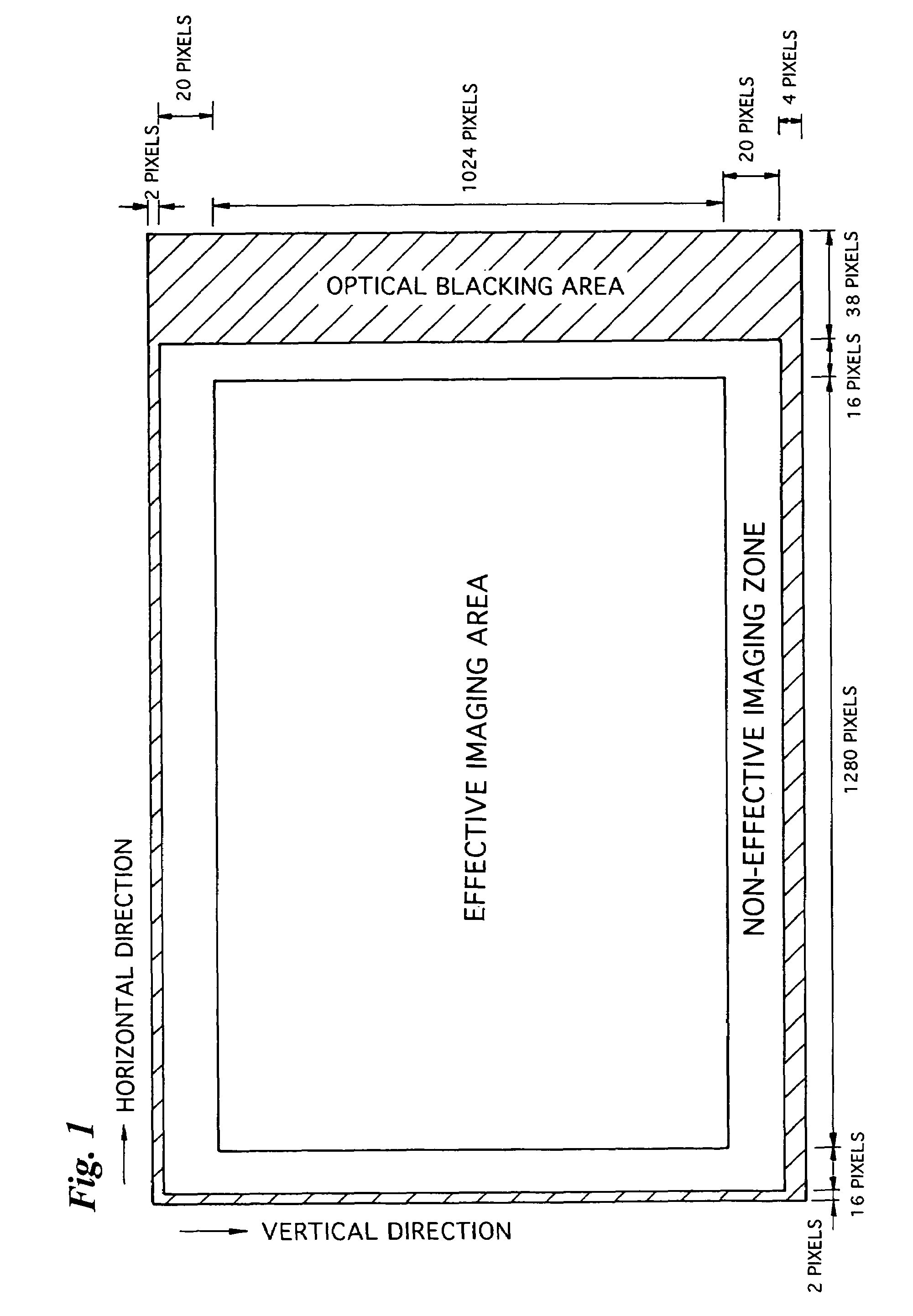
[0063]FIG. 1 illustrates the entire read-out area of an image sensing device (solid-state electronic image sensing device) such as a CCD.

[0064]An effective imaging area is formed substantially over the entirety of the read-out area and has 1280 pixels in the horizontal direction and 1024 pixels in the vertical direction. The image of a subject formed in the effective imaging area is an image represented by a video signal read out of the effective imaging area.

[0065]A non-effective imaging zone is formed about the perimeter of the effective imaging area. The non-effective imaging zone is an area in which the video signal obtained is not used in generating the image of a subject. The non-effective imaging zone has a width of 16 pixels in the horizontal direction on both the left and right sides of the effective imaging area and a width of 20 pixels in the vertical direction on both the top and bottom sides of the effective imaging area.

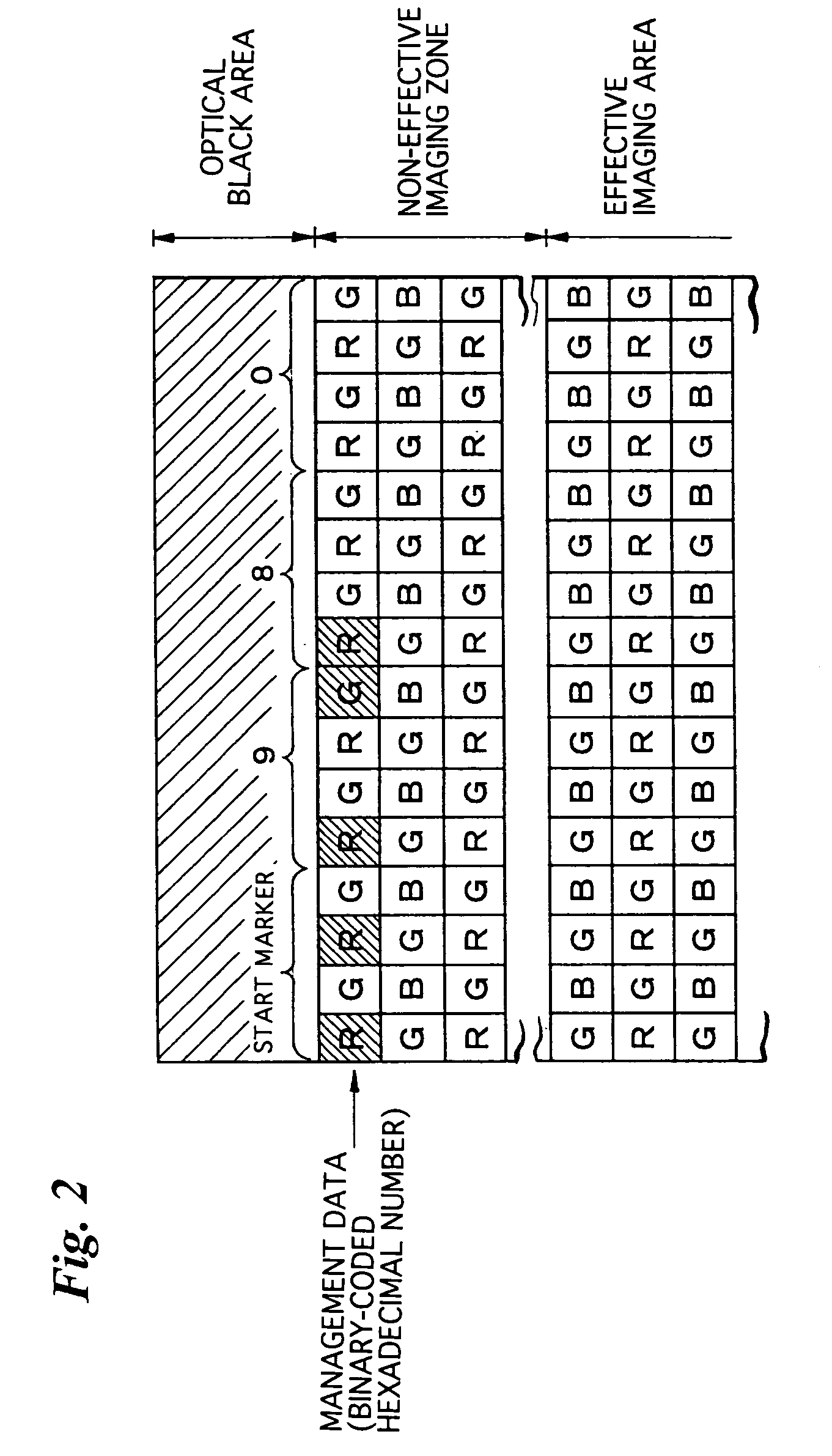
[0066]Further, an optical bla...


PUM


Abstract

Management data for managing an image sensing device can be read from the device even after the device has been mounted. To accomplish this, the management data is recorded in a non-effective imaging zone that surrounds an effective imaging area in the read-out area of the image sensing device. The non-effective imaging zone is a zone from which an output signal is not used in generating a sensed target image. The management data can be sensed from the signal output by the image sensing device. In another aspect, management data for managing an image sensing device can be read from the device even after the device has been mounted on a circuit board. To accomplish this, the management data is recorded on a protective glass, which covers the device, using an ink that reflects infrared radiation. A target image having a uniform pattern is sensed using a light source whose emission includes infrared radiation, and the image obtained by such sensing is displayed on a display. The portion of the obtained target image that is the management data appears darker than other portions. The management data is obtained by reading the darkened portion.

Description

CROSS REFERENCE TO RELATED APPLICATION[0001]This application is a Divisional of U.S. application Ser. No. 09 / 384,553, filed Aug. 27, 1999 now U.S. Pat. No. 6,791,619, which is expressly incorporated herein by reference in its entirety.BACKGROUND OF THE INVENTION[0002]1. Field of the Invention[0003]This invention relates to a system and method for recording data that is for the management of solid-state electronic image sensing devices, a system and method for sensing the management data of solid-state electronic image sensing devices, and a solid-state electronic image sensing device.[0004]2. Description of the Related Art[0005]Formed on the front side of a solid-state electronic image sensing device is an imaging area on which the image of a subject is formed. The imaging area is covered with a transparent material such as glass.[0006]Management data (product name, typical specifications, revision number, lot number, applied voltage, date of manufacture, etc.) is recorded on the so...

Claims


Application Information

Patent Timeline
IPC IPC(8): H04N5/225B42D15/00H01L21/00H04N5/33H01L27/14H04N5/372
CPCH04N5/335H04N3/155H01L27/14621H01L27/14818H01L27/14623H04N25/702
Inventor MISAWA, TAKESHI
Owner FUJIFILM CORP
Why Eureka
Try Eureka