

User-defined hierarchies of user-defined classes of graphical objects in a graphical modeling environment
a graphical modeling environment and user-defined hierarchy technology, applied in the field of computing devices, can solve the problems of complex models that are difficult to create and maintain, use such graphical representations to simplify the creation and maintenance of models of complex systems, and duplication of effort, so as to facilitate the creation and maintenance of models.
- Summary
- Abstract
- Description
- Claims
- Application Information
AI Technical Summary
Benefits of technology
Problems solved by technology
Method used
Image

Examples
Embodiment Construction
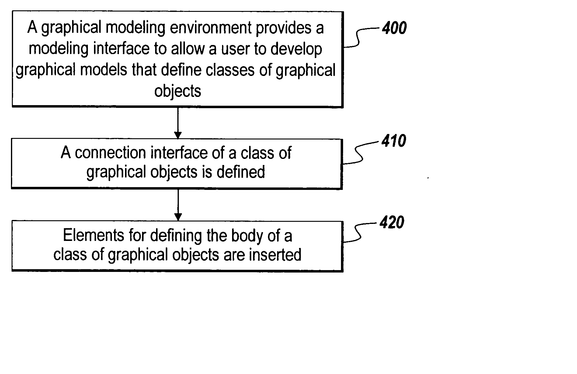
[0038] Embodiments of the present invention allow a user to graphically define a hierarchy of user-defined classes of graphical objects and the behavior and properties of the classes. Instances of the classes of graphical objects may be executable and may be implemented in an executable graphical model. The hierarchy of classes of graphical objects may include one or more root classes of graphical objects. The hierarchy of classes of graphical objects may also include one or more classes of graphical objects that are descendants of the root class or root classes. The hierarchy may include parent classes and children classes, such that the hierarchy of classes of graphical objects may include multiple generations and a class of graphical objects may be both a parent and a child class. Further, embodiments of the present invention permit a class to have multiple parents. Such an embodiment is said to support multiple inheritance. A child class of graphical objects is a direct descenda...
PUM
 Abstract
Description
Claims
Application Information