Pneumatic tire

Active Publication Date: 2008-04-24
TOYO TIRE & RUBBER CO LTD
View PDF7 Cites 12 Cited by
  • Summary
  • Abstract
  • Description
  • Claims
  • Application Information

AI Technical Summary

Benefits of technology

[0011]When the tire is new, since the main groove extends in the tire circumferential direction in a linear manner, the generation of uneven wear at the rib can be inhibited. Since the bottom of the main groove extends in a zigzag manner, as the wear progresses, due to the main groove's extending in the zigzag manner, the traction performance and the braking performance of the tire are improved. Also, when the protrusions appear on the tread surface as the wear progresses, due to the protrusions, the traction performance and the braking performance are improved.
[0012]Even when the stones are caught in the main groove, due to the protrusions, the stones can be inhibited from proceeding into the groove bottom direction, thereby capable of preventing the catching of stones. Further, since the protrusions are not continuous and are arranged with spaces, the drainage performance of the main groove is not damaged. Further, since the protrusions are joined to the sidewall, even when the stones proceed into, they are not deformed easily and therefore, no cracks are generated at the joining portion between the groove bottom and the protrusions.
[0013]The concave portions of the sidewalls of the main groove have higher rigidity compared with the convex portions thereof, and since the protrusions are further provided, the rigidity gets higher all the more. Therefore, by forming sipes or notches extending from the concave portion to the inner side of the rib in the tire width direction, the rigidity of the concave portions of the sidewalls is lowered to narrow the rigidity difference with that of the convex portions, thereby inhibiting the uneven wear.
[0015]By providing protrusions at both sidewalls, the effect of preventing the catching of stones, the traction performance and the braking performance at the time of progressing wear are improved.

Problems solved by technology

When stones are caught in the grooves and cannot be removed therefrom, sometimes the stones proceed in the direction of groove bottoms, thereby damaging the groove bottoms.
When the stones proceed further into the grooves, belt layers and auxiliary belt layers are damaged, enhancing the risk of causing failure.
In particular, main grooves are likely to be damaged since deformation of the grooves by tire rotation is little.
However, when the protrusions with heights capable of satisfactorily preventing the generation of the catching of stones are provided at the center in the bottom of the main grooves, the drainage performance of the main grooves get greatly degraded.
Also, cracks are likely to occur at the joining portion between the protrusion and the groove bottom since the protrusion gets more deformable when the stones proceed into the grooves.
Therefore, it has been difficult to realize both improvement in the drainage performance and prevention of the catching of stones.

Method used


Image

  • Pneumatic tire
  • Pneumatic tire
  • Pneumatic tire

Examples


example

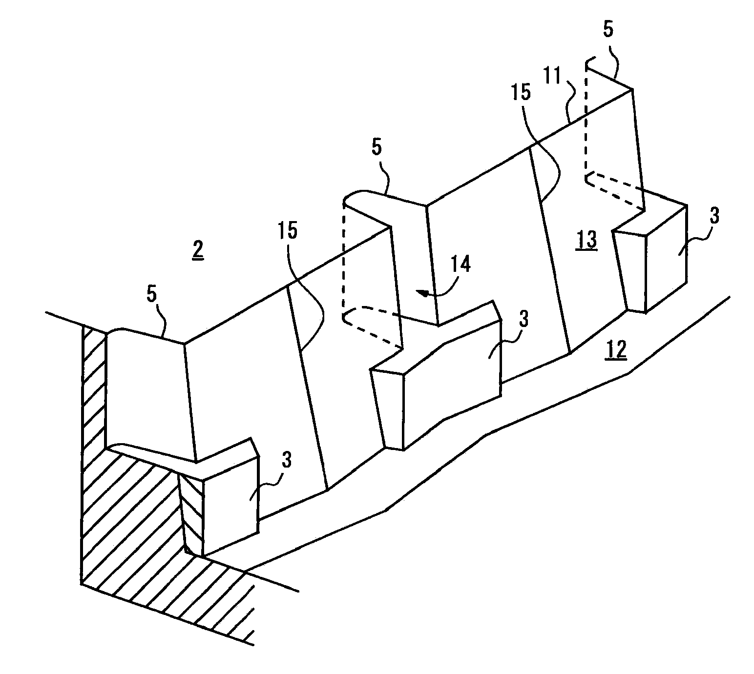
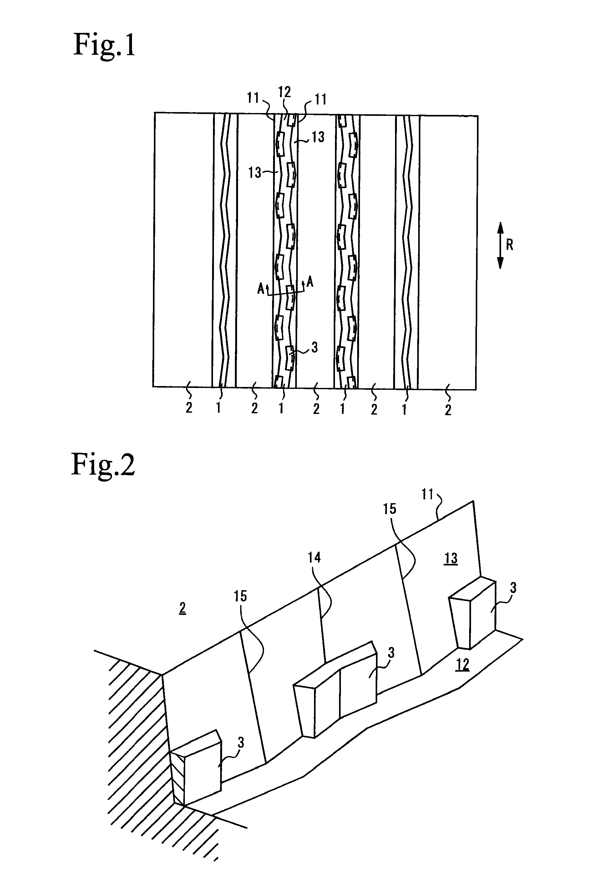
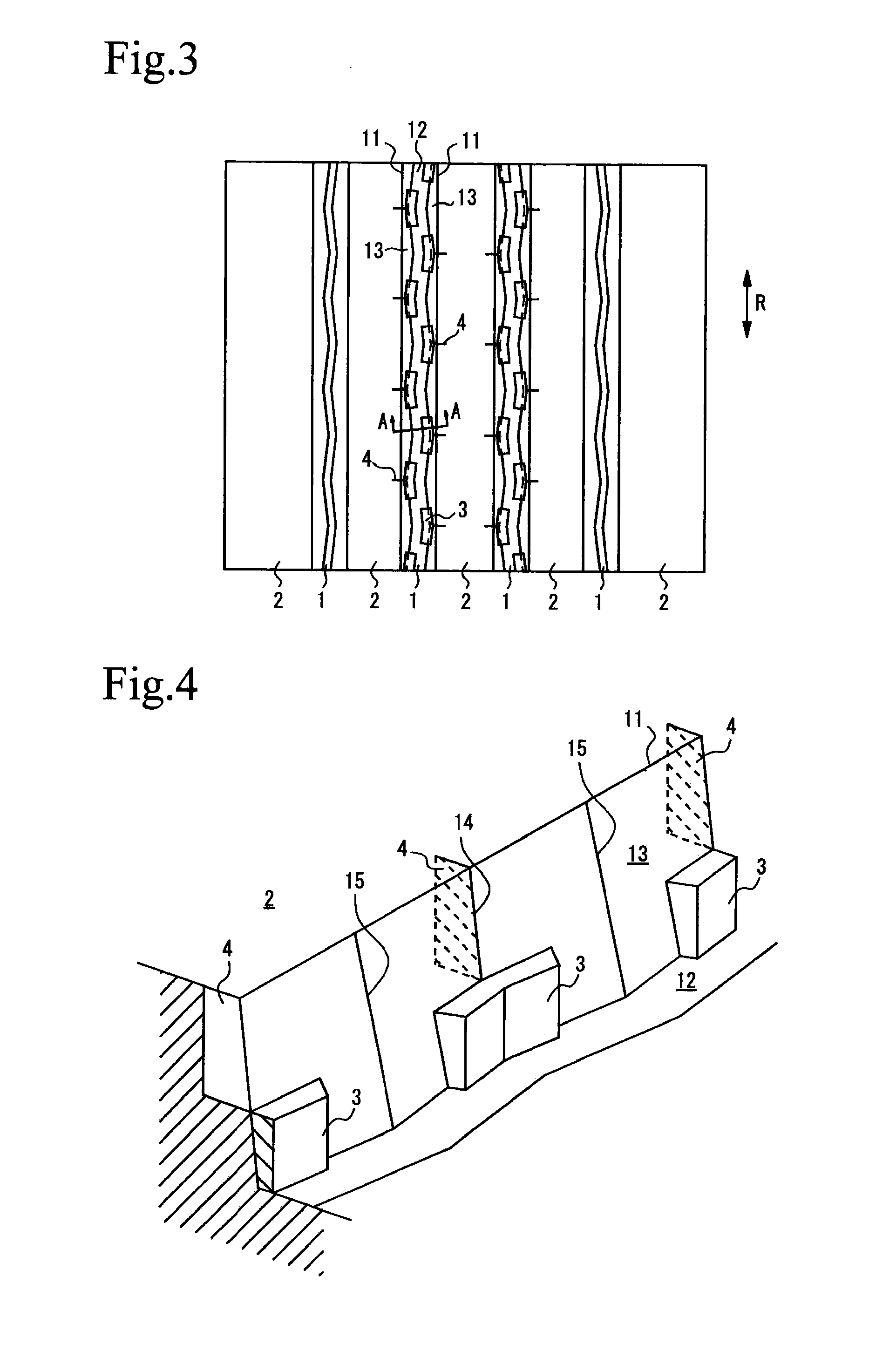
[0040]The pneumatic tires of the present invention of the Examples were test produced and the evaluation was made by installing the tires on a truck with a live load of 10 tons (axle constitution of 2-D). For information, the tread patterns of Examples 1 to 3 were the patterns shown in FIGS. 1, 3, and 5, respectively. The depth D of the main grooves 1 was 14.5 mm, the height H of the protrusion 3 is 3 mm, and W, W1, and W2 in FIGS. 8 to 10 were 7 mm, 4.5 mm, and 6.5 mm, respectively, and L1 and L2 were 23 mm and 17 mm, respectively, and the width of the ribs 2 was 38 mm. The length of the sipes 4 of the Example 2 was 2.5 mm, and the length of the notches 5 of the Example 3 was 4 mm, and the opening width of the notches 5 at the sidewall 13 was 5.5 mm.

[0041]The tires of the Conventional Examples 1 to 3 were the tires that had the same patterns as those of the Examples 1 to 3 but were not provided with the protrusions. However, the tire of the Conventional Example 2 is provided with t...


PUM


Abstract

In the pneumatic tire in which not less than three main grooves 1 extending in the tire circumferential direction R are formed and ribs 2 are formed by the main grooves 1, upper edges 11 of the main groove 1 when the tire is new extend in a linear manner in the tire circumferential direction R, the bottom 12 of the main groove 1 extends in a zigzag manner in the tire circumferential direction R, the sidewalls 13 of the main groove 1 is provided with concave portions and convex portions, and in the concave portion of at least one of the sidewalls 13 of the main groove 1, the protrusions 3 that is joined to the bottom 12 of the main groove 1 and to the sidewall 13. Further, the pneumatic tire may be provided with sipes or notches that extend from the concave portion to the inner side of the rib 2 in the tire width direction.

Description

[0001]The description of this application claims benefit of priorities based on Japanese Patent Application No. 2006-288276 and Japanese Patent Application No. 2006-288277, the entire same contents of which are incorporated by reference herein.BACKGROUND OF THE INVENTION[0002]1. Field of the Invention[0003]The present invention relates to a pneumatic tire, and in more detail, the present invention relates to the pneumatic tire that inhibits the generation of so-called stone-biting, a phenomenon in which stones are caught in the tire grooves and cannot be removed, while securing the traction performance and the drainage performance.[0004]2. Description of the Prior Art[0005]In order to obtain desired performances including drainage performance, traction performance, braking performance, and the like, main grooves extending in the tire circumferential direction and transverse grooves extending in the tire width direction are formed on a tread. When stones are caught in the grooves and...

Claims


Application Information

Patent Timeline
IPC IPC(8): B60C11/04
CPCB60C11/12B60C11/13B60C11/047Y10S152/901Y10S152/03Y10S152/90B60C11/045B60C2011/1338
Inventor FUJIOKA, TSUYOSHI
Owner TOYO TIRE & RUBBER CO LTD
Why Eureka
Try Eureka