Pipe Joint

a pipe joint and pipe technology, applied in the direction of sleeve/socket joints, joints with sealing surfaces, fluid pressure sealed joints, etc., to achieve the effect of adaptability of the flange part, improving and accelerating the assembly of the pipe joint, and solving the problem of pipe joints that cannot be formed by hand

Inactive Publication Date: 2008-04-24
SUNDHOLM GORAN
View PDF27 Cites 13 Cited by
  • Summary
  • Abstract
  • Description
  • Claims
  • Application Information

AI Technical Summary

Benefits of technology

[0008] The solution of the invention has numerous significant advantages. By using an adaptable flange part of a joint according to the invention, a very versatile solution for forming a pipe joint is achieved. On the one hand, the flange part adapts for use with different collar parts. On the other hand, it adapts to different shape variations or malformations in connection with collars. By using a multi-element flange part, it is possible to consider flange thickness requirements while still achieving an adaptability of the flange part of the joint relative to the collar. By using a flange part formed from segments it is further possible to significantly improve and accelerate the assembly of a pipe joint. The joint can more easily be formed directly from the side. On the other hand, the segments can better adjust themselves against the collar. By using a spacer element between the flanges to be placed on different sides of the joint, it is possible to keep the flanges at a desired distance from each other during the assembly, thus facilitating the mounting work. By using a centering element, it is possible to achieve mutual centering of the pipe sections to be joined, which improves the quality of the joint and further facilitates the mounting work. By using a flexible sleeve element, a combined element that works both as a centering element and a spacer element is produced. By using multi-element flange parts attached together, advantages are achieved during the assembly and, on the other hand, the formation of the flange pack is facilitated. By implementing the joining using a binding agent, such as an elastic glue, e.g. silicone or the like, an advantageous and easy-to-use solution for forming the flange part pack is achieved. By using between the pipe sections to be joined a planar sealing with an adhesive surface on one side, allowing it to be attached to one of the pipe sections before the mounting, the mounting work can be further facilitated and accelerated. By using a compensating element, such as a flexible washer, a reliable structure is obtained for the tightening of the joint and, on the other hand, for compensation of an angular or planar difference between the tightening elements and flange parts.

Problems solved by technology

Such a joint has the drawback that the flange parts have to be so formed that their shape on the side facing towards the collar corresponds to the shape of the collar.
A further problem is that the collar or the flange may undergo variations of shape, which may cause problems e.g. regarding the tightness of the joint.

Method used


Image

  • Pipe Joint
  • Pipe Joint
  • Pipe Joint

Examples


Embodiment Construction

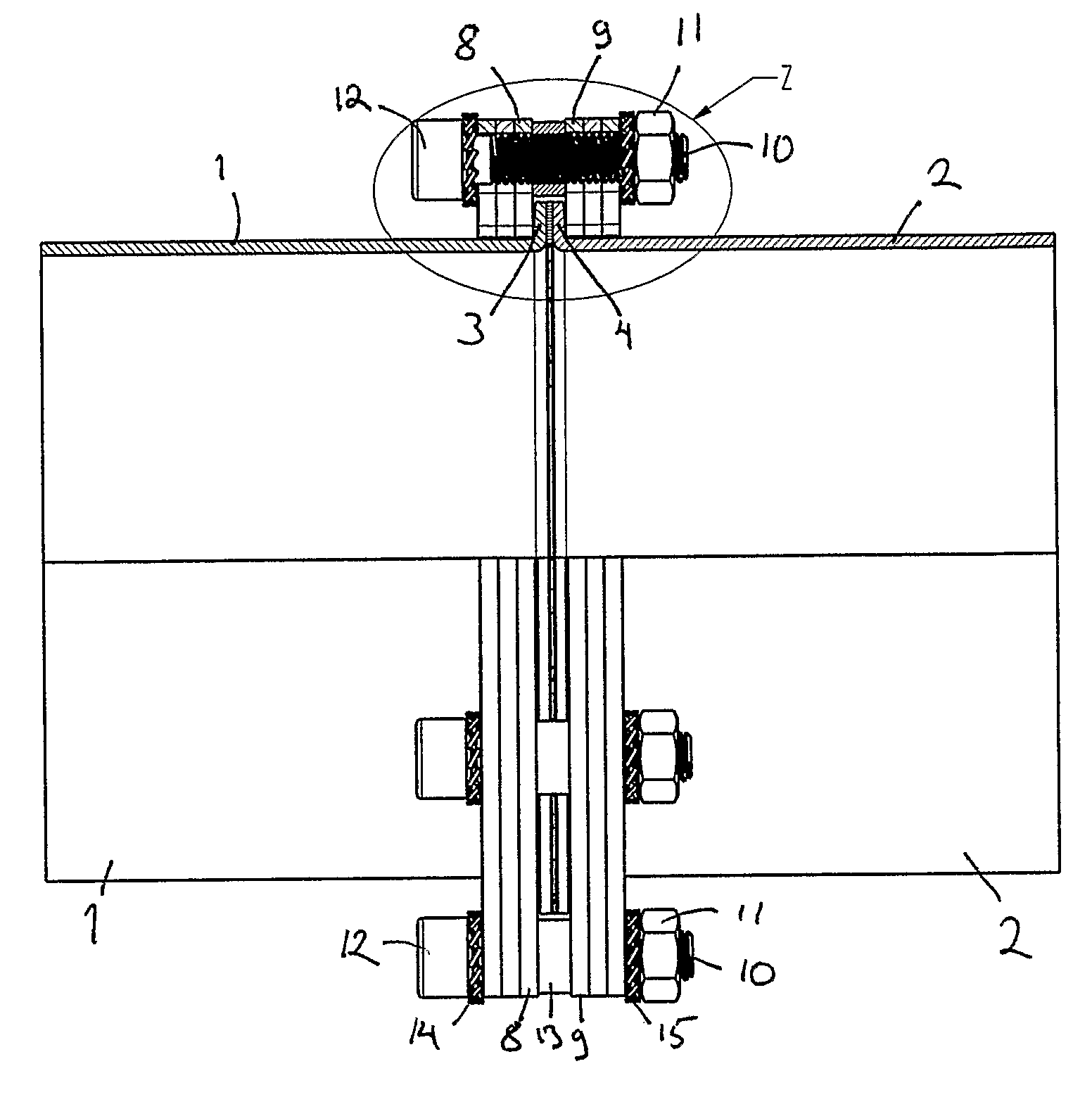
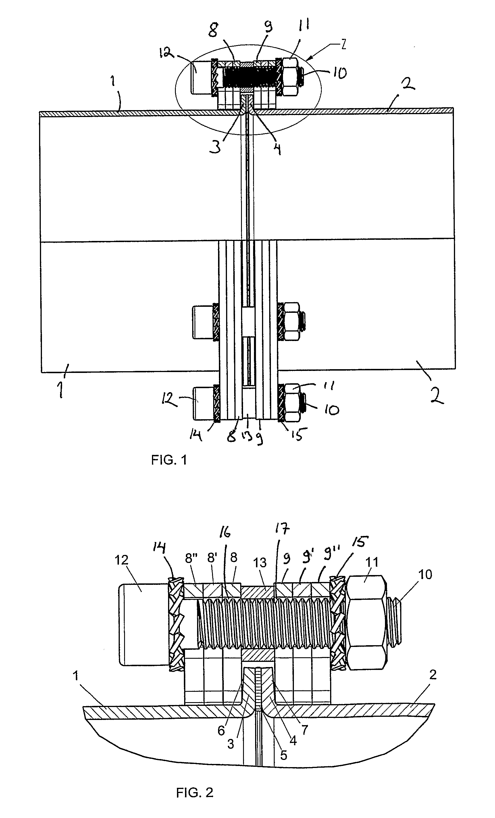
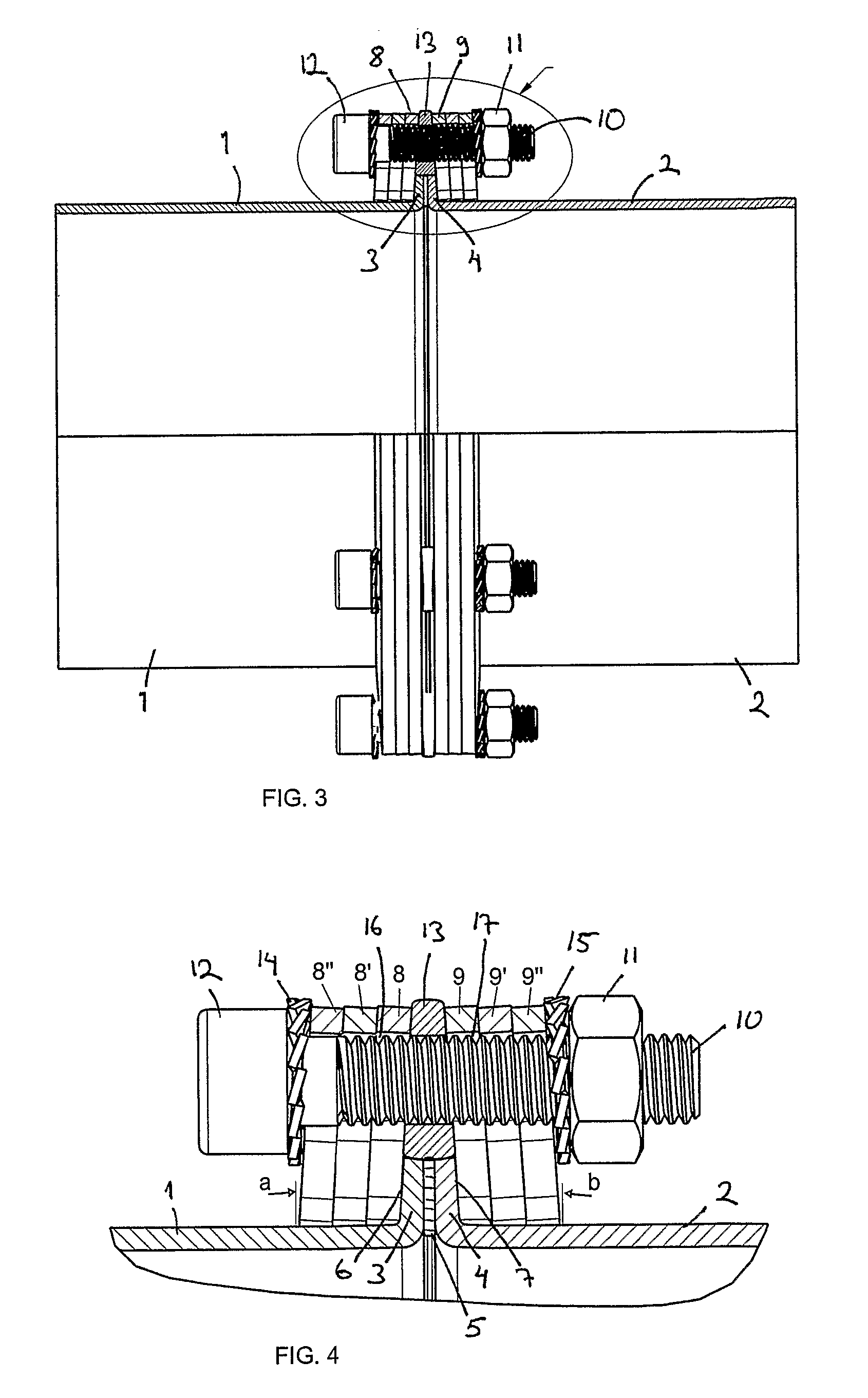
[0022]FIGS. 1 and 2 present a pipe joint according to the invention before the tightening of the joint. FIGS. 3 and 4 show the joint of FIGS. 1 and 2 when tightened.

[0023] There are numerous ways of forming a collar at the end of a pipe section. Some of these are described in publication GB 2202022 A, among others. Naturally, the collar can also be formed in other ways, even by welding. The figure shows a collar type in which the back surface of the collar, i.e. the surface against which the flange part will be placed, is somewhat slanting.

[0024] In the pipe joint, pipe sections 1 and 2 are joined together by means of a flange joint by pressing the pipe sections together end to end by collars 3, 4 formed at the ends of the pipe sections. Arranged between the joint surfaces of the collars is preferably a sealing element 5. The pipe sections 1, 2 are pressed against each other by means of flange parts 8, 9 on the side facing away from the joint surfaces of the collars, i.e. by the b...


PUM


Abstract

A pipe joint consisting of the end portions of pipe sections (1, 2) to be joined together, said end portions having a collar (3, 4) preferably protruding substantially perpendicularly, and of flange parts (8, 9) placed on different sides of the collars relative to the junction and tightened by means of suitable fastening elements, such as screws (10) and nuts (11). The flange part (8, 9) has been arranged to be adaptable against the shoulder of the collar (3, 4), most suitably against its back surface (6, 7), at least when the joint is being tightened.

Description

BACKGROUND OF THE INVENTION [0001] The present invention relates to a pipe joint as defined in the preamble of claim 1, consisting of the end portions of pipe sections to be joined together, said end portions having a collar protruding preferably perpendicularly, and flange portions which, as seen from the junction, are placed on different sides of the collars and tightened by means of applicable fastening elements, such as screws and nuts. [0002] For butt connection of pipes, flange joints are generally used. For these it is required that the ends of both pipes to be joined are provided with a collar, typically e.g. a collar substantially perpendicular to the longitudinal axis of the pipe and receiving the flange part pressed against it. The collars of the pipe sections to be joined together remain between the flanges. The flanges are provided with holes through which tightening elements, such as screws or bolts, are arranged and the joint is tightened with nut elements. There are ...

Claims


Application Information

Patent Timeline
Patent Type & Authority Applications(United States)
IPC IPC(8): F16L23/028F16L23/032
CPCF16L23/032F16L23/0283F16L23/028
Inventor SUNDHOLM, GORAN
Owner SUNDHOLM GORAN
Why Eureka
Try Eureka