Imaging apparatus and imaging control method

a technology of imaging control and imaging apparatus, applied in the field of imaging apparatus, can solve problems such as image may become unnatural

Inactive Publication Date: 2008-04-24
XACTI CORP
View PDF5 Cites 81 Cited by
  • Summary
  • Abstract
  • Description
  • Claims
  • Application Information

AI Technical Summary

Benefits of technology

[0019]In addition, a first imaging control method according to the present invention is an imaging control method that is used in an imaging apparatus having an image sensor for obtaining a picture image from an optical image that is projected to the image sensor through an optical system, and an image moving portion for moving the optical image on the image sensor. The method includes a motion detecting step for detecting a movement on the picture image of a moving subject that appears in the optical image, and a control step for controlling, during an exposure period after a predetermined operation, the image moving portion in the direction of canceling the movement of the moving subject on the image sensor due to a movement of the moving subject in a real space, based on a movement of the moving subject detected in advance. Length of the exposure period is set based on the movement of the moving subject detected in advance.
[0020]In addition, a second imaging control method according to the present invention is an imaging control method that is used in an imaging apparatus having an image sensor for obtaining a picture image from an optical image that is projected to the image sensor through an optical system, and an image moving portion for moving the optical image on the image sensor. The method includes a motion detecting step for classifying subjects appearing in the optical image into a moving subject and a background, and for detecting movements on the picture image of the moving subject and the background, and a control step for controlling, during an exposure period after a predetermined operation, the image moving portion in the direction of canceling the movement of the moving subject on the image sensor due to a movement of the moving subject in a real space and a movement of the imaging apparatus, based on a movement of the moving subject detected in advance. Length of the exposure period is set based on the movements of the moving subject and the background detected in advance.

Problems solved by technology

If the “flow blur degree” is too large, the image may become unnatural.

Method used


Image

  • Imaging apparatus and imaging control method
  • Imaging apparatus and imaging control method
  • Imaging apparatus and imaging control method

Examples


first embodiment

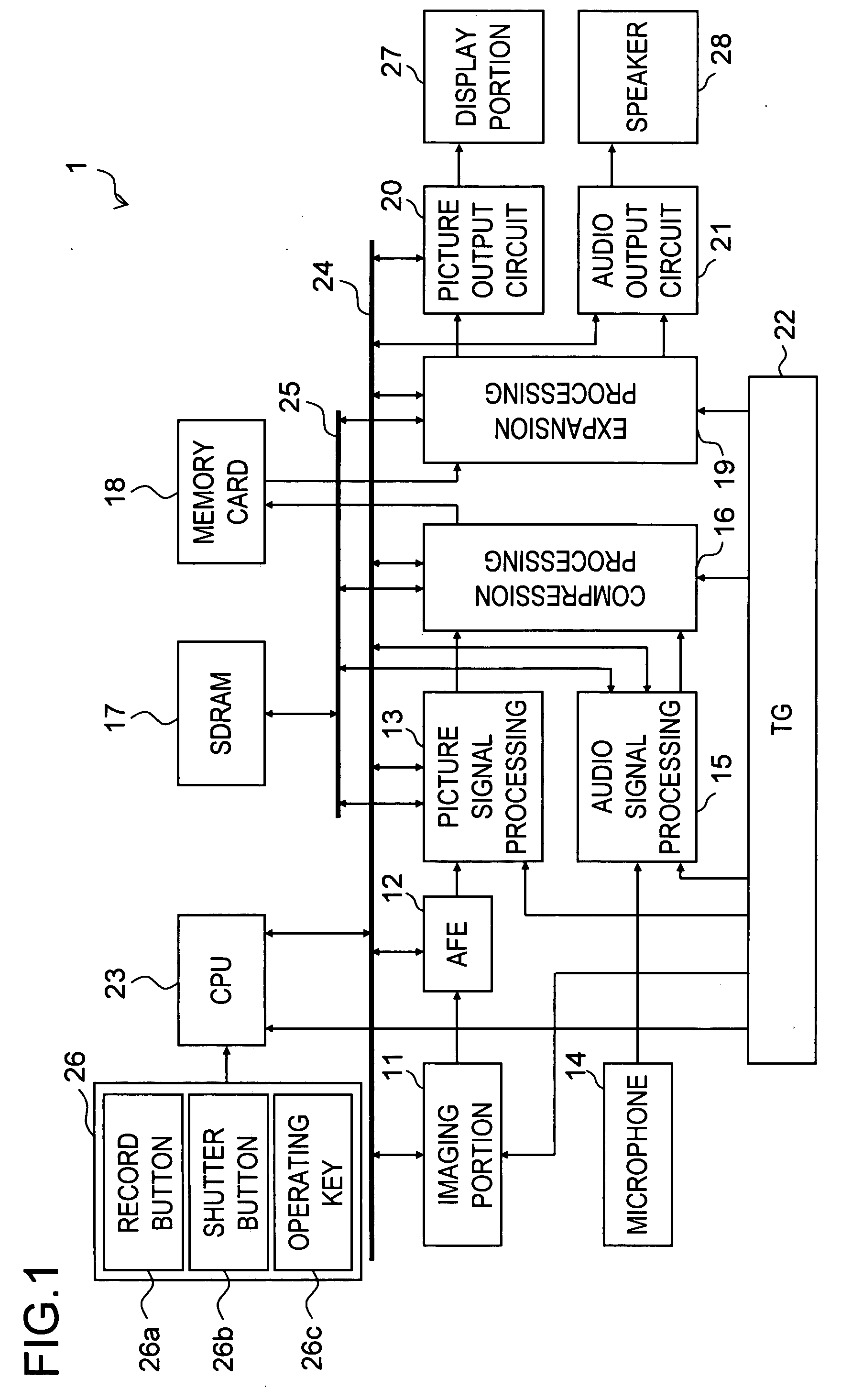
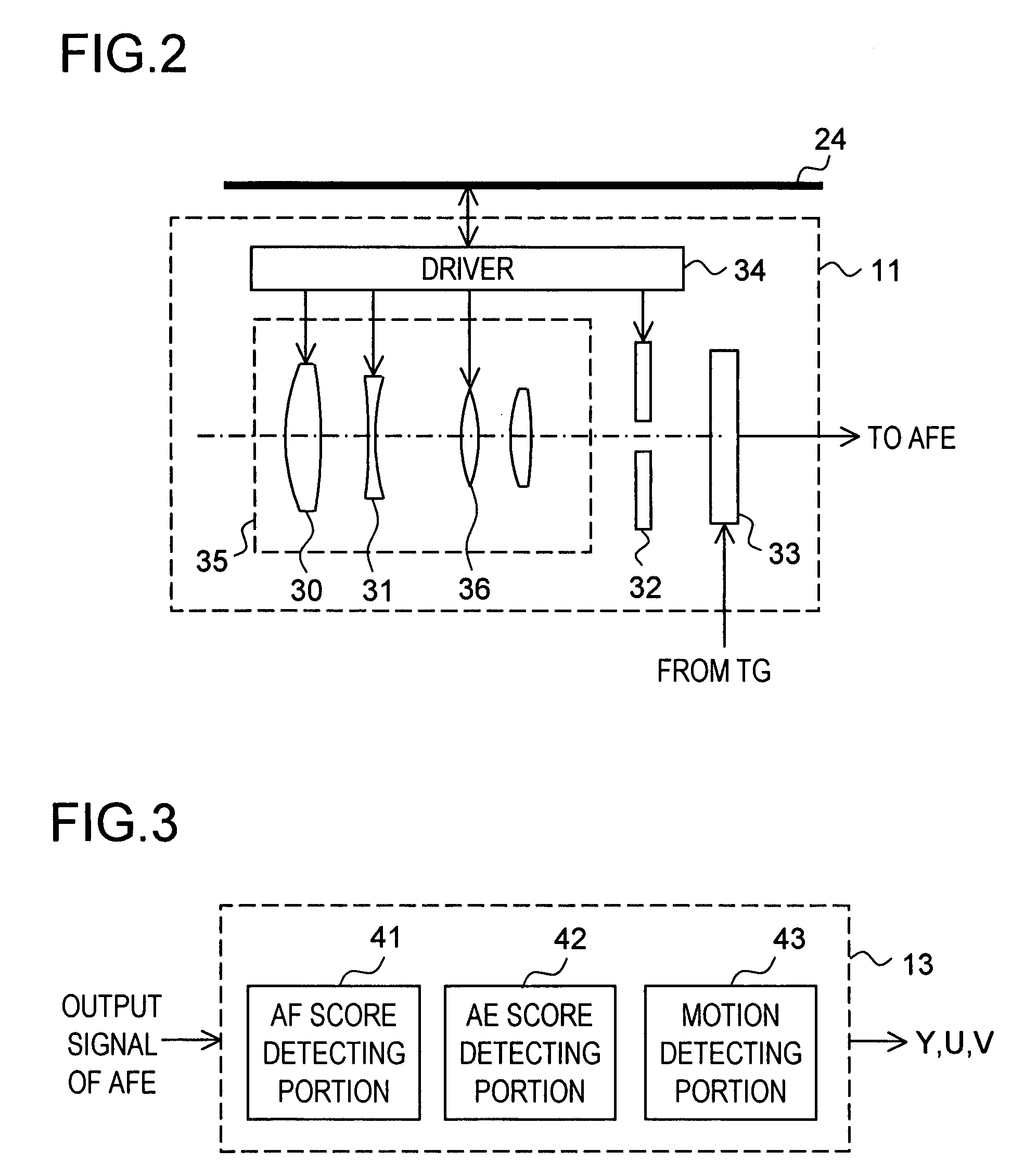
[0048]First, a first embodiment of the present invention will be described. FIG. 1 is a general block diagram of an imaging apparatus 1 according to an embodiment of the present invention. The imaging apparatus 1 is a digital video camera, for example. The imaging apparatus 1 is capable of obtaining moving pictures and still pictures. It is also capable of shooting a still picture while shooting a moving picture simultaneously.

[0049]The imaging apparatus 1 includes an imaging portion 11, an AFE (Analog Front End) 12, a picture signal processing portion 13, a microphone 14, an audio signal processing portion 15, a compression processing portion 16, an SDRAM (Synchronous Dynamic Random Access Memory) 17 as an example of an internal memory, a memory card (memory portion) 18, an expansion processing portion 19, a picture output circuit 20, an audio output circuit 21, a TG (timing generator) 22, a CPU (Central Processing Unit) 23, a bus 24, a bus 25, an operating portion 26, a display po...

second embodiment

[0143]Next, a second embodiment of the present invention will be described. A general block diagram of the imaging apparatus according to the second embodiment is the same as that shown in FIG. 1. Therefore, the imaging apparatus according to the second embodiment is also denoted by the reference numeral 1. The structures and the operations of individual portions of the imaging apparatus 1 according to the second embodiment are basically the same as those according to the first embodiment. Therefore, overlapping descriptions of the similar portions will be omitted. The descriptions in the first embodiment are applied to the second embodiment as long as no contradiction arises.

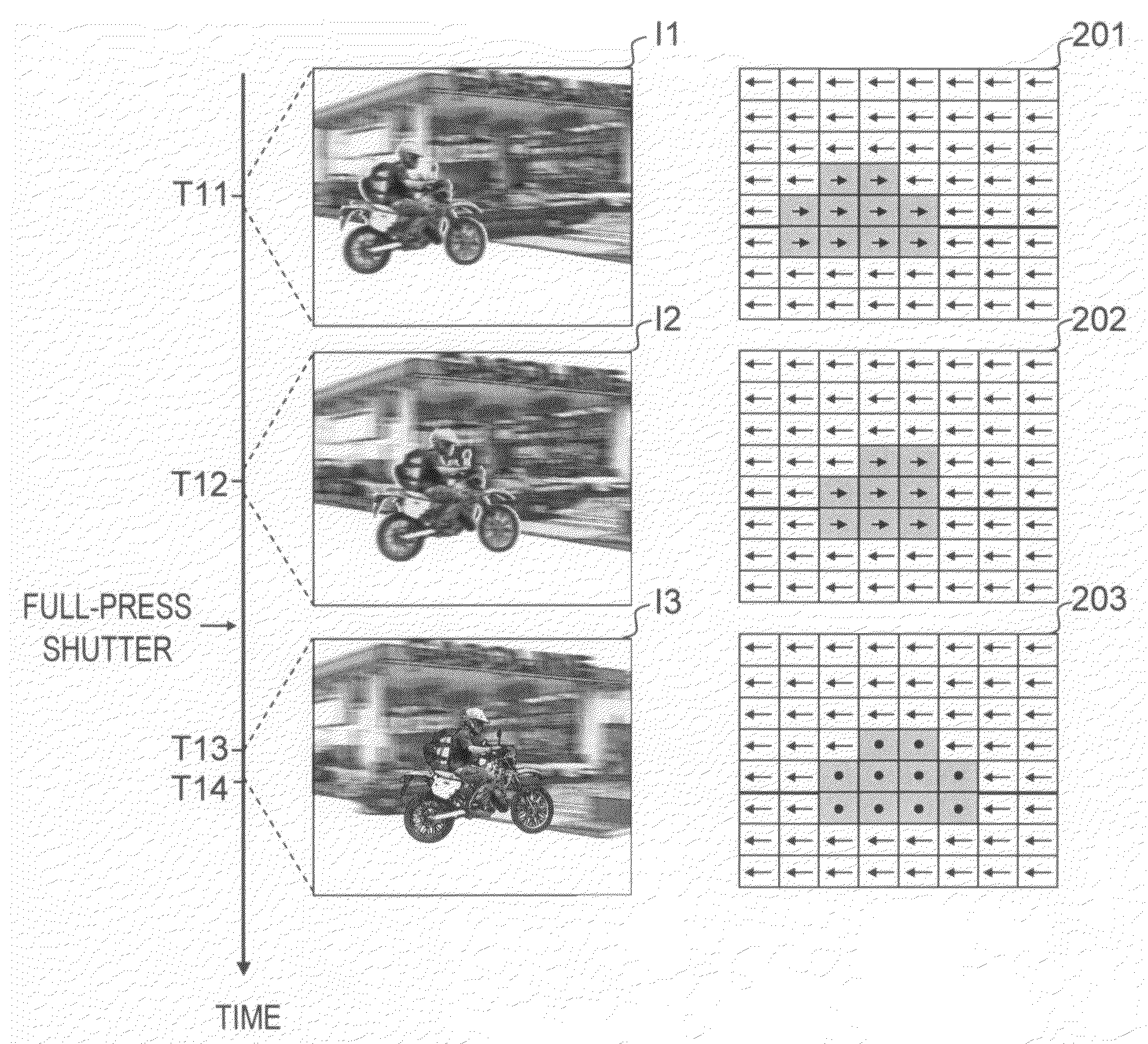
[0144]The function of imaging by the follow shot according to the first embodiment is predicated on that the imaging apparatus 1 is fixed. In the second embodiment, however, it is supposed that the photographer performs panning or tilting operation of the imaging apparatus 1 when the follow shot is performed so...


PUM


Abstract

The imaging apparatus includes an image sensor for obtaining a picture image from an optical image that is projected to the image sensor through an optical system, an image moving portion for moving the optical image on the image sensor, a motion detecting portion for detecting a movement on the picture image of a moving subject that appears in the optical image, and a control portion for controlling, during an exposure period after a predetermined operation, the image moving portion in the direction of canceling the movement of the moving subject on the image sensor due to a movement of the moving subject in the real space, based on a movement of the moving subject detected in advance. The control portion sets length of the exposure period based on the movement of the moving subject detected in advance.

Description

[0001]This nonprovisional application claims priority under 35 U.S.C. § 119(a) on patent application No. 2006-288538 filed in Japan on Oct. 24, 2006 and patent application No. 2007-236432 filed in Japan on Sep. 12, 2007, the entire contents of which are hereby incorporated by reference.BACKGROUND OF THE INVENTION[0002]1. Field of the Invention[0003]The present invention relates to an imaging apparatus such as a digital still camera or a digital video camera, and it also relates to an imaging control method that is used by the imaging apparatus.[0004]2. Description of Related Art[0005]There is a special imaging technique called “follow shot” that is used for emphasizing fast speed of a vehicle or the like running in a car race or the like. Conventionally, the follow shot is performed by setting an exposure time that can generate necessary background blur in accordance with the speed of the moving subject such as a vehicle and by moving the imaging apparatus horizontally so as to purs...

Claims


Application Information

Patent Timeline
Patent Type & Authority Applications(United States)
IPC IPC(8): G03B13/00G03B7/00G03B5/02G03B7/097H04N5/232H04N101/00
CPCG03B5/02G03B7/00H04N5/2353H04N5/2254H04N5/23212G03B39/00H04N23/673H04N23/73
Inventor MORI, YUKIO
Owner XACTI CORP
Why Eureka
Try Eureka