
Endoscopic camera illumination system and method

a camera and illumination system technology, applied in the field of endoscopic camera systems, can solve the problems of endoscope, excessive heat, endoscope, etc., and achieve the effect of maintaining image quality

Inactive Publication Date: 2014-02-20
ARTHREX
View PDF5 Cites 69 Cited by
  • Summary
  • Abstract
  • Description
  • Claims
  • Application Information

AI Technical Summary

Benefits of technology

The present invention is a camera system with an illumination system that adjusts its output to the minimum level required to maintain image quality. The system has an illumination controller that supplies a drive current to the illumination system, which in turn controls the amount of light provided during each frame of the exposure period. The system also has an image processor that adjusts the images based on the amount of drive current received to compensate for changes in light color. Additionally, the system may have a storage device for storing image processing parameters and a light source that emits light of a first wavelength band, which is then converted to light of a second wavelength band by phosphors. Overall, the invention improves image quality and control over the illumination system during endoscopic procedures.

Problems solved by technology

However, the output of a white LED is difficult to efficiently couple to an optical fiber or other waveguide.
The generation of substantial input power causes the generation of heat which must be dissipated and which often makes an endoscope, and the user's hand touching it, excessively hot.
Moreover, the substantial power required negatively impacts the size and portability of the endoscope because mains power or substantial battery resources are required.
If the optical coupling of the LED to an optical fiber or other waveguide is eliminated by mounting the white LED at the distal tip of the endoscope, the heat from the LED itself raises the tip temperature, and the temperature of patient tissue at the operative site, to unacceptable levels.
However, unacceptable levels of heat are often generated from the excitation light source.
Moreover, substantial power is still required for the excitation light source.

Method used


Image

  • Endoscopic camera illumination system and method
  • Endoscopic camera illumination system and method
  • Endoscopic camera illumination system and method

Examples


Embodiment Construction

[0026]In the following description of the preferred embodiments, reference is made to the accompanying drawings which show by way of illustration specific embodiments in which the invention may be practiced. Wherever possible, the same reference numbers will be used throughout the drawings to refer to the same or like parts. It is to be understood that other embodiments may be utilized and structural and functional changes may be made without departing from the scope of the present invention.

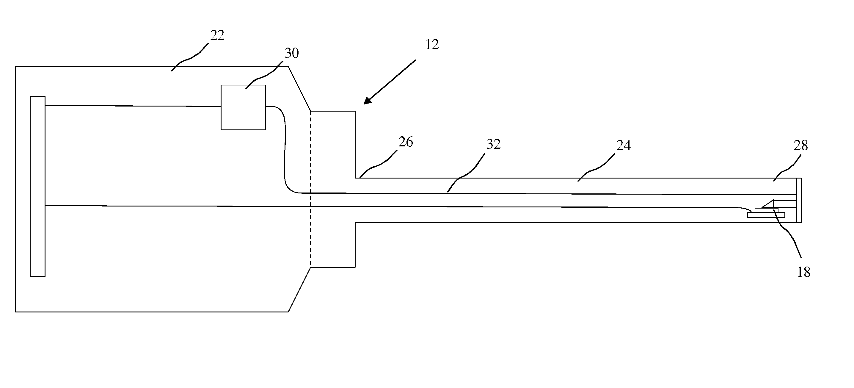
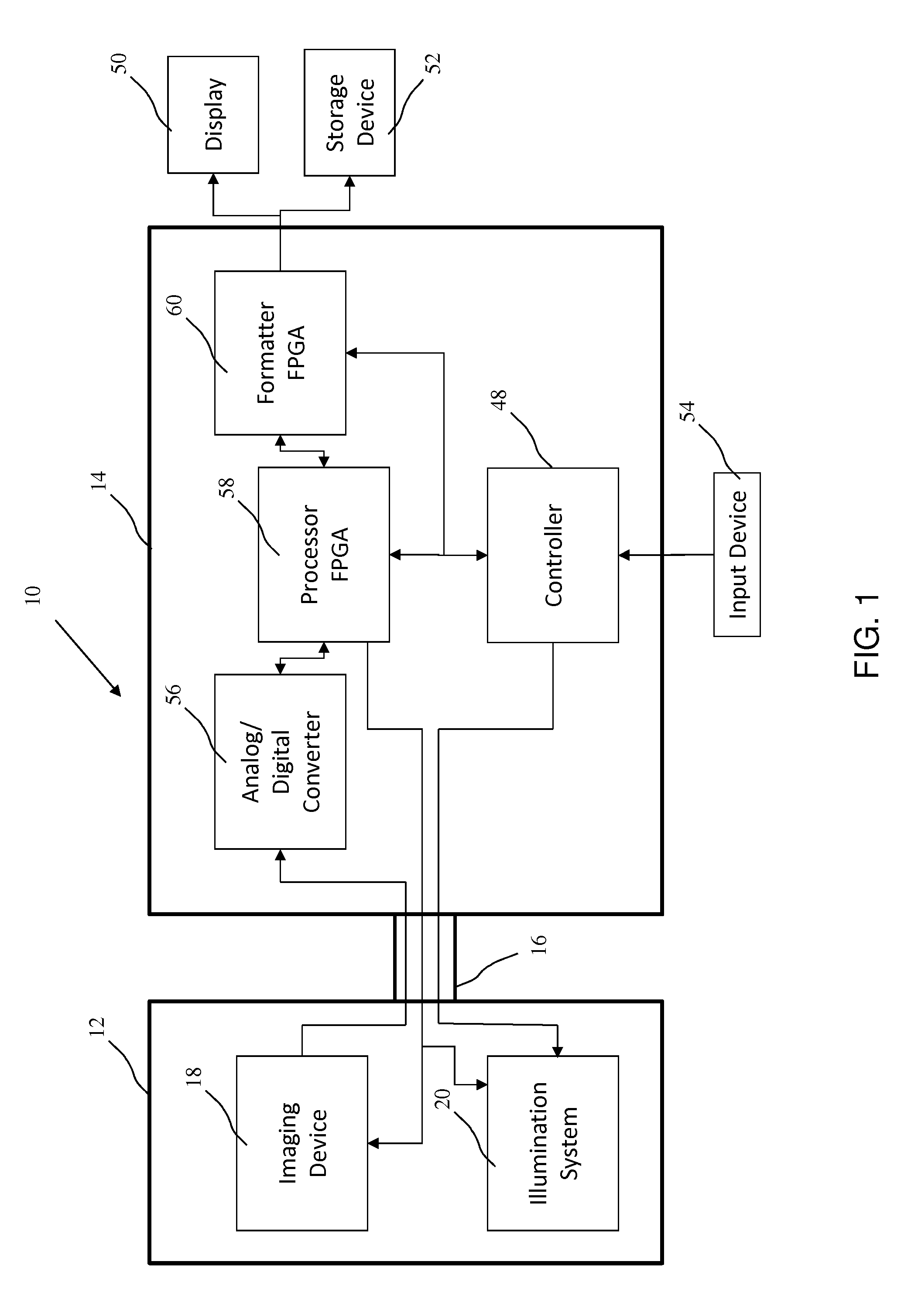
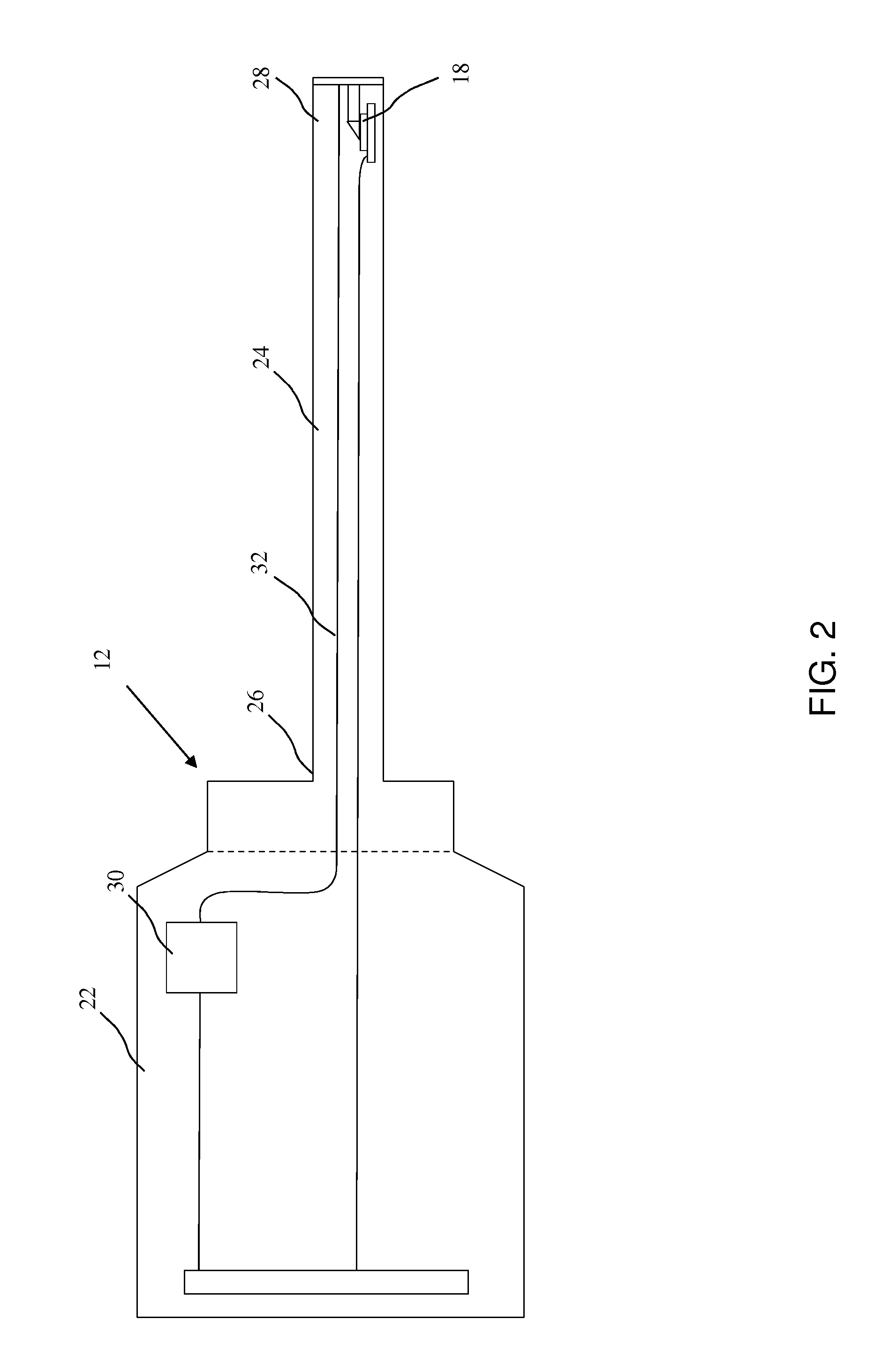
[0027]An endoscopic imaging system 10 according to an embodiment of the present invention is shown in FIG. 1. The endoscopic imaging system 10 allows for internal features of a body of a patient to be viewed without the use of traditional, fully invasive surgery. Additionally, the endoscopy system may be used for imaging of hard to reach parts of structures or in other applications where direct optical viewing is compromised.

[0028]The endoscopic imaging system 10 has a camera head 12 and a camer...


PUM


Abstract

An endoscopic camera system having an imaging device for taking images during an exposure period at a predetermined number of frames per second; an illumination system for providing light for the imaging device; and an illumination controller that supplies a drive current to the illumination system, the illumination controller altering the drive current to the illumination system so light is only provided for a portion of each image frame corresponding to the exposure period and for a second portion of each frame outside of the exposure period.

Description

BACKGROUND OF THE INVENTION[0001]This invention relates generally to endoscopic camera systems and, more particularly, to illumination systems for endoscopic camera systems.[0002]Endoscopic camera systems are used for seeing inside the body of a patient. A typical endoscopic camera system has an illumination system for illuminating the inside of a body cavity and a camera for capturing images of that cavity. Endoscopic camera systems are known in which white light emitting diodes (“LED”) are used as light sources. Light from the white LED may be passed to distal tip of the endoscope using an optical fiber or other waveguide.[0003]However, the output of a white LED is difficult to efficiently couple to an optical fiber or other waveguide. Consequently, to achieve adequate light at the distal tip of the endoscope, input power must be substantial. The generation of substantial input power causes the generation of heat which must be dissipated and which often makes an endoscope, and the...

Claims


Application Information

Patent Timeline
IPC IPC(8): A61B1/045A61B1/07A61B6/00A61B1/06
CPCA61B1/00036A61B1/063A61B1/0653A61B1/0669A61B1/0684A61B1/07A61B1/0655
Inventor D'ALFONSO, DAVIDKENNEDY, BRUCE LAURENCESPEIER, CRAIG
Owner ARTHREX
Learn More