Time of flight system capable of increasing measurement accuracy, saving power and/or increasing motion detection rate and method thereof

a technology of time flight and measurement accuracy, applied in the field of time flight system and method, can solve the problems of lower measurement accuracy of time flight system, inability of time flight system to save power, and lower motion detection rate, so as to increase measurement accuracy, increase measurement accuracy, and save power

Active Publication Date: 2011-12-15
SAMSUNG ELECTRONICS CO LTD
View PDF7 Cites 77 Cited by
  • Summary
  • Abstract
  • Description
  • Claims
  • Application Information

AI Technical Summary

Benefits of technology

[0005]An embodiment of the present invention provides a method of time of flight capable of increasing measurement accuracy. The method includes transmitting invisible light to detect an object; recording a time interval of the invisible light traveling to the object and reflected from the object to a sensor; and adjusting an emission period of the invisible light and an exposure period of the sensor according to the time interval.
[0006]Another embodiment of the present invention provides a time of flight system capable of increasing measurement accuracy. The time of flight system includes a light source, a sensor, and a processor. The light source is used for transmitting invisible light toward an object. The sensor is used for receiving reflected light reflected by the object. And the processor is coupled to the sensor for recording a time interval of the invisible light traveling to the object and reflected from the object to the sensor, and adjusting an emission period of the invisible light and an exposure period of the sensor according to the time interval.
[0007]Another embodiment of the present invention provides a method of time of flight capable of saving power. The method includes transmitting invisible light to detect an object; recording a time interval of the invisible light traveling to the object and reflected from the object to a sensor; and adjusting emission intensity of the invisible light according to the time interval.
[0008]Another embodiment of the present invention provides a time of flight system capable of saving power. The time of flight system includes a light source, a sensor, and a processor. The light source is used for transmitting invisible light toward an object. The sensor is used for receiving reflected light reflected by the object. The processor is coupled to the sensor for recording a time interval of the invisible light traveling to the object and reflected from the object to the sensor, and adjusting emission intensity of the invisible light according to the time interval.
[0009]Another embodiment of the present invention provides a method of time of flight capable of increasing motion detection rate. The method includes transmitting invisible light to detect an object; recording a time interval of the invisible light traveling to the object and reflected from the object to a sensor; and adjusting a main sensing range of the sensor according to the time interval.
[0010]Another embodiment of the present invention provides a time of flight system capable of increasing motion detection rate. The time of flight system includes a light source, a sensor, and a processor. The light source is used for transmitting invisible light toward an object. The sensor is used for receiving reflected light reflected by the object. The processor is coupled to the sensor for recording a time interval of the invisible light traveling to the object and reflected from the object to the sensor, and adjusting a main sensing range of the sensor according to the time interval.

Problems solved by technology

However, the time of flight system neither dynamically adjusts distance detecting range with the distance between the object and the time of flight system nor dynamically adjusts an exposure period of a sensor included in the time of flight system, so measurement accuracy of the time of flight system is lower.
In addition, the time of flight system also cannot dynamically adjust emission intensity of the light source with the distance between the object and the time of flight system, so the time of flight system cannot save power.
In addition to the above drawbacks, the time of flight system also cannot dynamically adjust main sensing range of the sensor with the distance between the object and the time of flight system, so the time of flight system needs to sense a larger range, resulting in lower motion detection rate.

Method used


Image

  • Time of flight system capable of increasing measurement accuracy, saving power and/or increasing motion detection rate and method thereof
  • Time of flight system capable of increasing measurement accuracy, saving power and/or increasing motion detection rate and method thereof
  • Time of flight system capable of increasing measurement accuracy, saving power and/or increasing motion detection rate and method thereof

Examples


Embodiment Construction

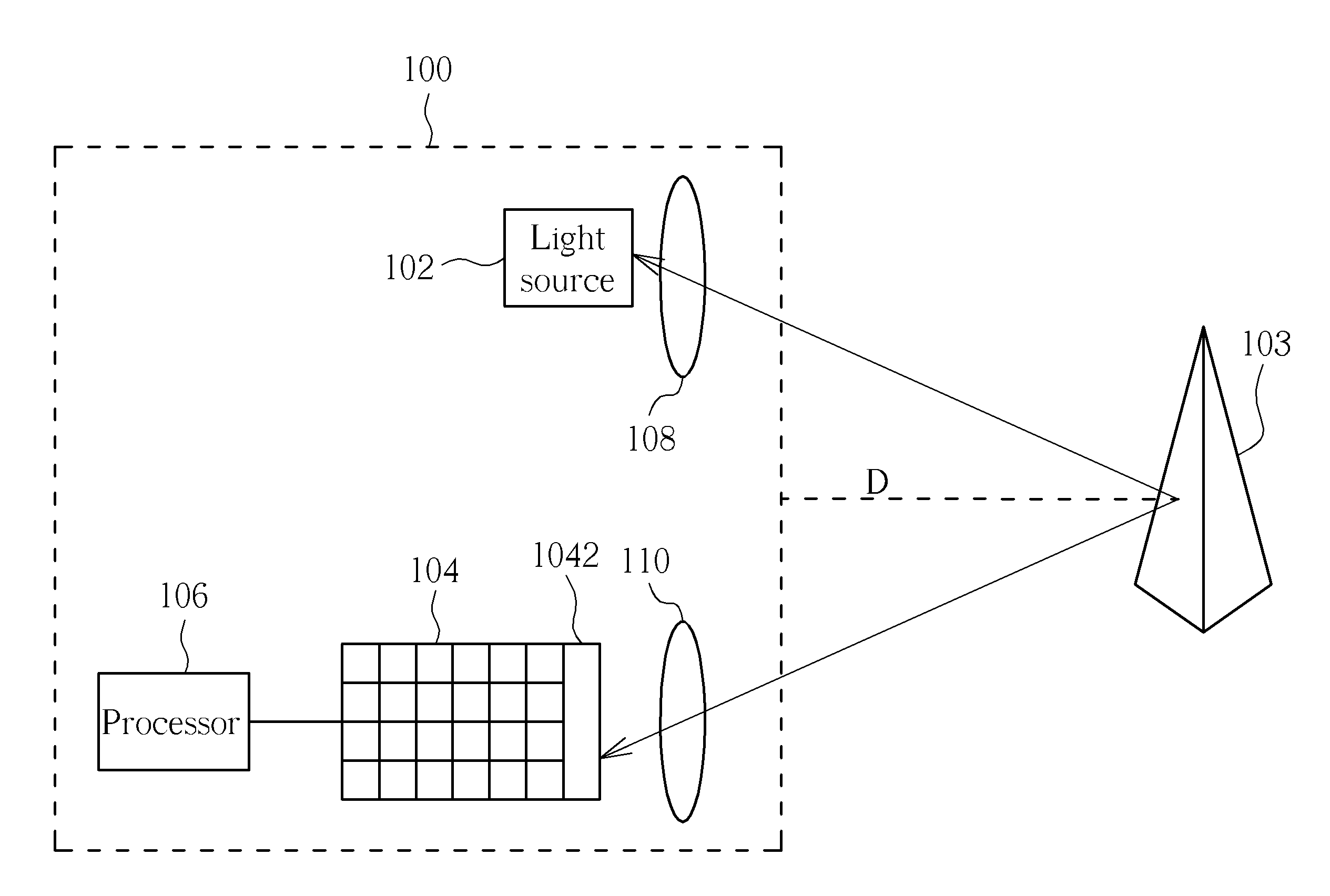
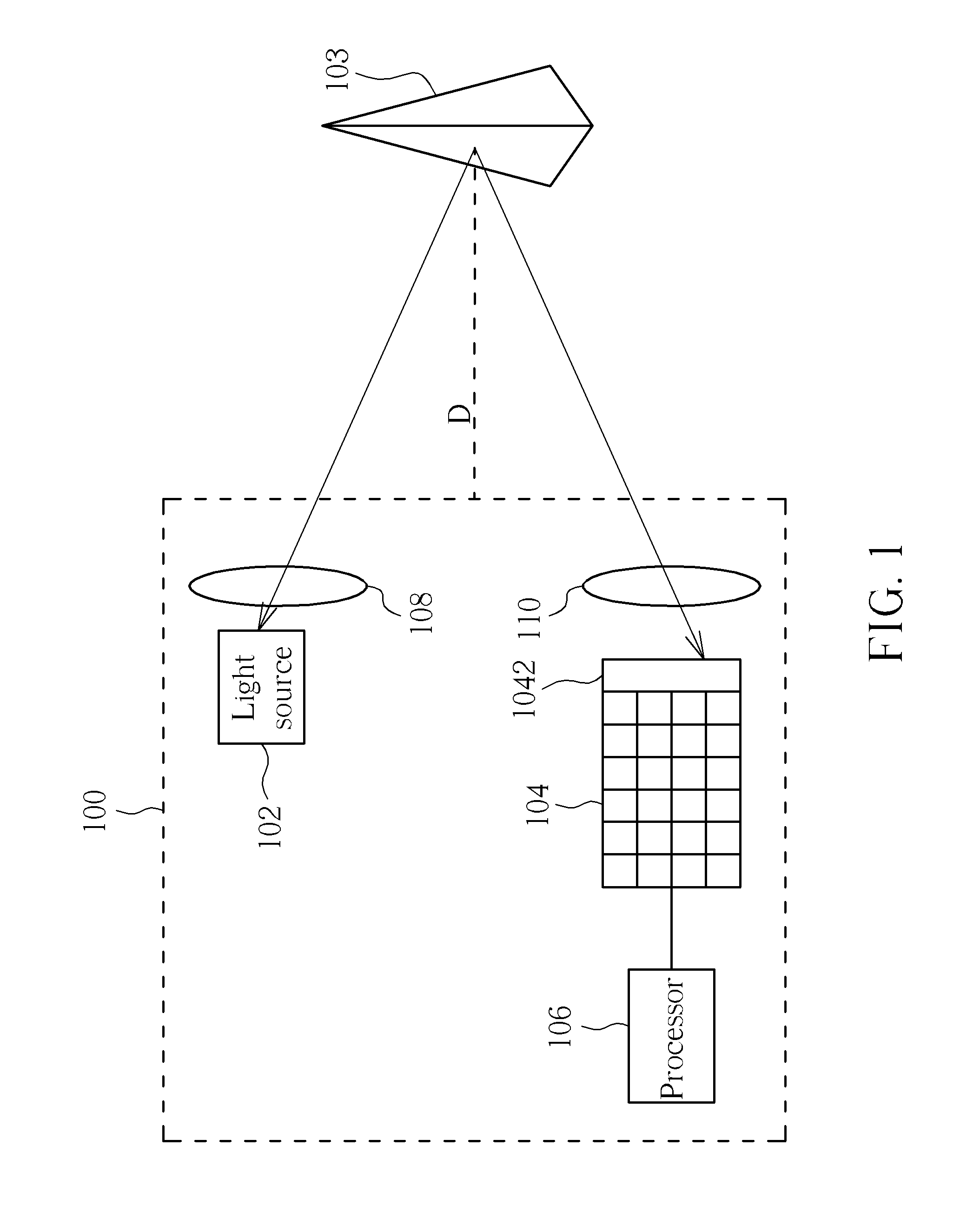
[0019]Please refer to FIG. 1. FIG. 1 is a diagram illustrating a time of flight system 100 capable of increasing measurement accuracy according to an embodiment of the present invention. The time of flight system 100 includes a light source 102, a sensor 104, and a processor 106. The light source 102 is used for transmitting invisible light to detect an object 103, where the light source 102 is an IR light emitting diode or an IR laser source. The sensor 104 is a sensing array for receiving reflected light reflected by the object 103. When the light source 102 transmits invisible light (infrared light) toward a surface of the object 103, the sensor 104 can determine a shape of the object 103 according to the reflected light. In addition, the sensor 104 further includes an IR filter 1042 for blocking light outside the IR range from entering the sensor 104. The processor 106 is coupled to the sensor 104 for recording a time interval T during which the invisible light travels to the ob...


PUM


Abstract

A light source is used for emitting an invisible light toward an object. The object reflects the invisible light and reflected light is formed, and a sensor is used for receiving the reflected light. A processor is coupled to the sensor for recording a time interval of the invisible light traveling from the light source to the object and reflected from the object to the sensor. Then, the processor estimates a measurement distance of the object according to the time interval, and adjusts an emission period of the light source, an exposure period of the sensor, intensity of the invisible light, and / or main sensing range of the sensor according to the measurement distance.

Description

BACKGROUND OF THE INVENTION[0001]1. Field of the Invention[0002]The present invention is related to a time of flight system and method thereof, and particularly to a time of flight system and related method capable of increasing measurement accuracy, and saving power and / or motion detection rate according to a time interval of detecting light traveling to the object and reflected from the object to the time of flight system.[0003]2. Description of the Prior Art[0004]In the prior art, a time of flight (TOF) system transmits detection light toward an object, and receives reflected light formed by the object reflecting the detection light. The time of flight system estimates a distance between the object and the time of flight system according to a time interval of the invisible light traveling to the object and being reflected by the object back to the time of flight system. However, the time of flight system neither dynamically adjusts distance detecting range with the distance betwe...

Claims


Application Information

Patent Timeline
Patent Type & Authority Applications(United States)
IPC IPC(8): G01C3/08H05B37/02G01S17/894
CPCG01S17/89G01S7/4918G01S17/894
Inventor KAO, MING-TSANHSU, EN-FENGWANG, CHUAN-WEI
Owner SAMSUNG ELECTRONICS CO LTD
Why Eureka
Try Eureka