Transfer Vehicle

a technology for transportation vehicles and vehicles, applied in the field of transportation vehicles, can solve the problems of increasing the cost of transportation items, increasing the dead weight of the vehicle, and increasing the cost of transportation

Inactive Publication Date: 2008-04-24
DEERE & CO
View PDF20 Cites 12 Cited by
  • Summary
  • Abstract
  • Description
  • Claims
  • Application Information

AI Technical Summary

Benefits of technology

[0010]According to the present invention, there is provided a transfer vehicle including an unloading conveyor having a variable drive of a simple technical construction intended to operate both in a stationary mode and in a loading and transport mode.

Problems solved by technology

This was able to be carried out with more powerful harvesting machines which, however, as a result also became more expensive.
Thus, during harvesting, every minute of stoppage is associated with high financial costs.
Transfer vehicles with high conveying capacity have, due to the large worm diameter, a correspondingly high dead weight.
The greater and heavier such transfer vehicles are designed to be, the more difficult it is for said transfer vehicles to be transported over fields, particularly in the loaded state.
Thus the capacity of conventional transfer vehicles may hardly be increased further.
The conveying capacity is, however, not only limited by the worm diameter and thus the weight of the conveyor worm but also by the speed thereof.
An increase in the speed of the conveyor worm results in a higher load of the grain to be conveyed and may result in damage to the cereal grains on the worm.
Thus losses associated with the quality of the harvest may be foreseen.
Additionally, the structural and manufacturing cost is correspondingly high, in order to ensure running of the heavy conveyor worms in a manner which is low in vibration.
This requires a relatively complicated construction.
Large step-down ratios are necessary which, in particular with the relatively frequently occurring torque impulses, are particularly critical and generally require overload clutches.
This leads to high loads when starting up the unloading conveyor again, which sometimes even makes starting up again impossible.

Method used


Image

  • Transfer Vehicle
  • Transfer Vehicle

Examples


Embodiment Construction

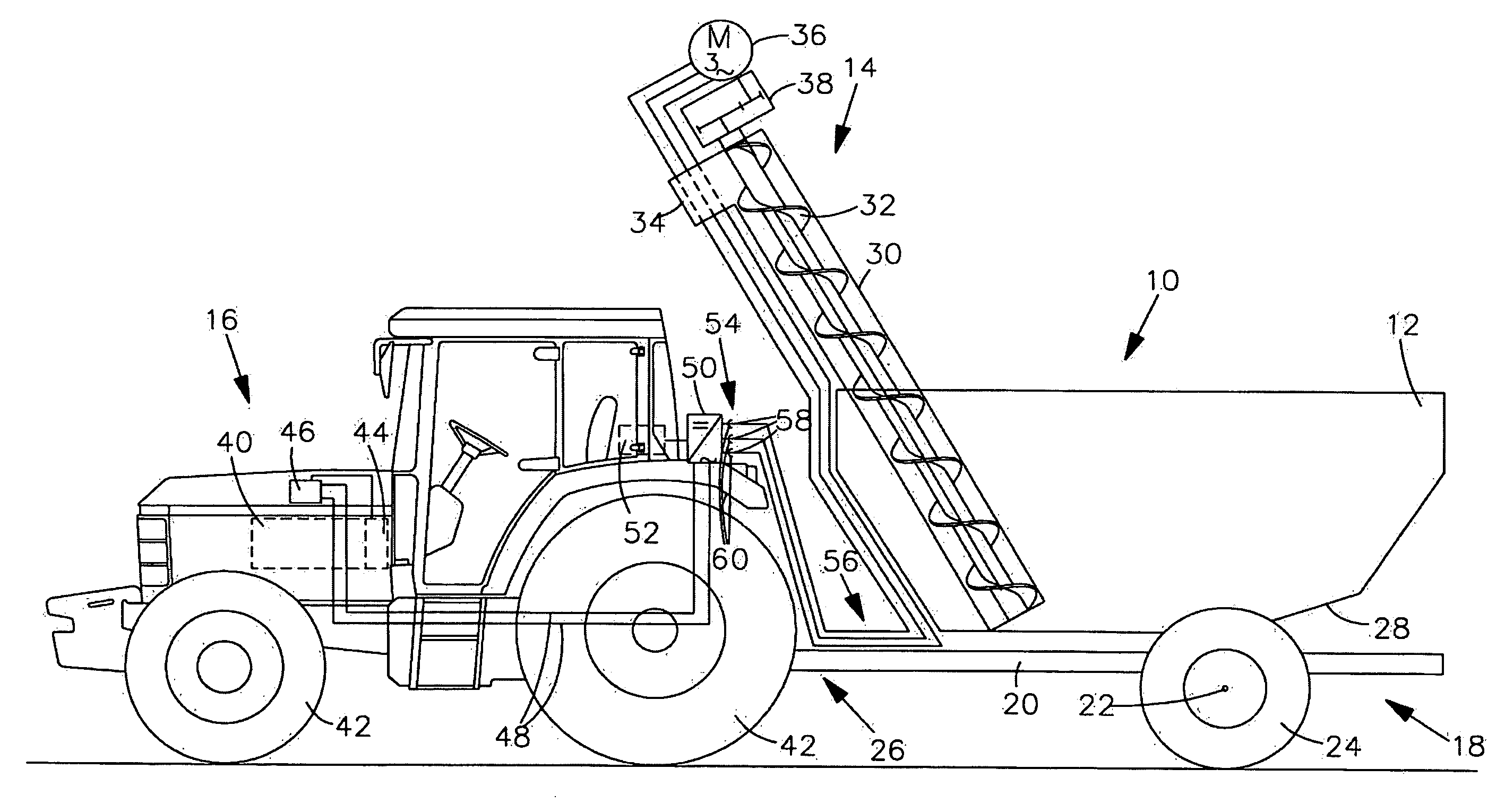
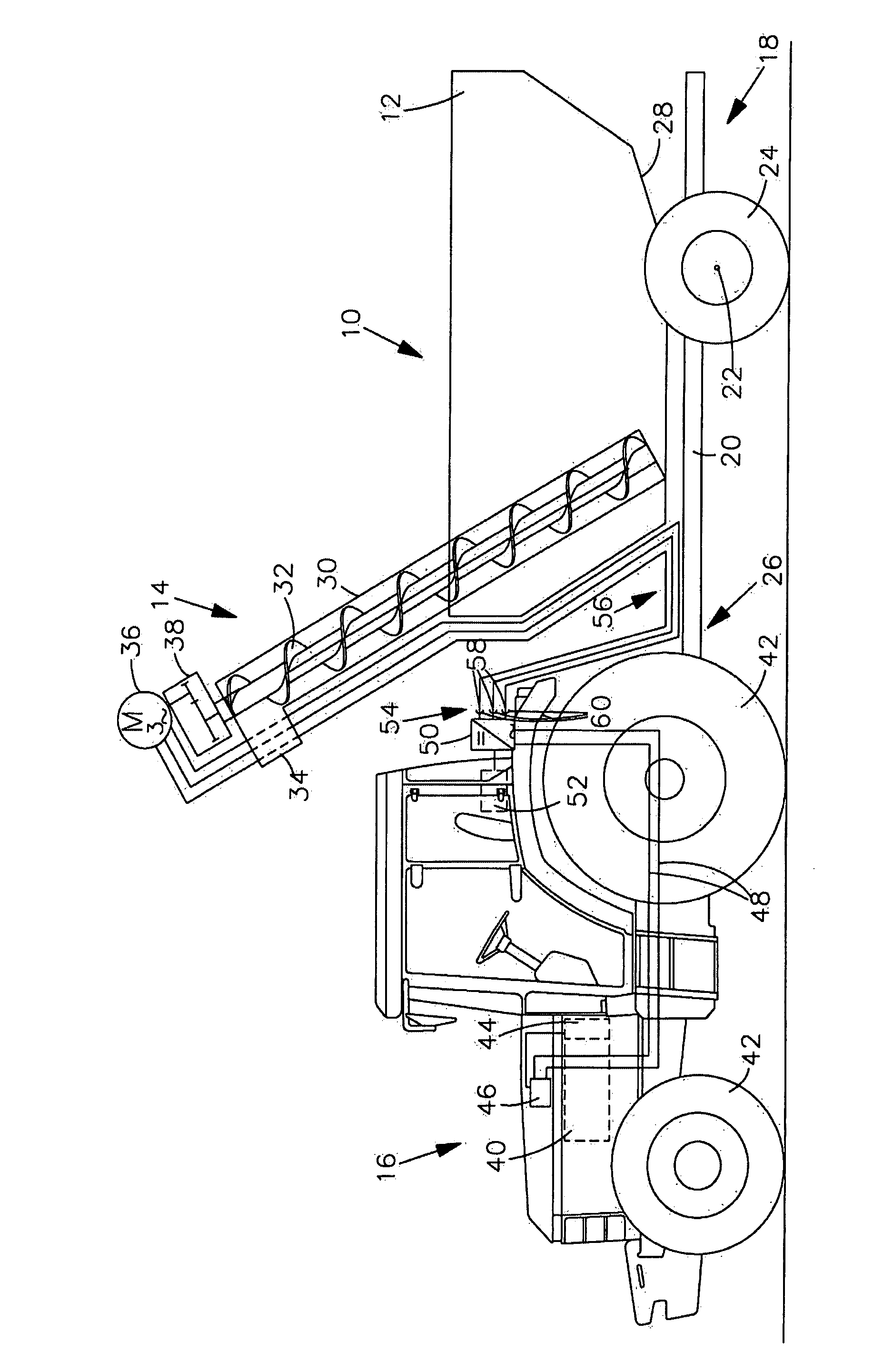
[0029]In the only figure, a transfer vehicle 10 is shown which comprises a container 12 for receiving bulk goods. Moreover, the transfer vehicle 10 comprises an unloading conveyor 14 for unloading the bulk goods (not shown) located in the container. The transfer vehicle 10 is coupled to a towing vehicle shown here as a tractor 16 and may be pulled thereby.

[0030]The transfer vehicle 10 comprises a container 12 of substantially prismatic configuration. The container 12 and the unloading conveyor 14 are constructed on a single-axle chassis 18. The chassis 18 comprises a frame 20 on which a continuous axle 22 having opposite ends respectively provided with a right and a left running wheel of which only the left wheel 24 is shown. The frame 20 comprises a towbar 26, only indicated schematically, which is designed for being attached to the tractor 16. It is only indicated schematically that the bottom wall 28 of the container 12 therefore extends over the entire length of the receiving co...


PUM


Abstract

A transfer vehicle is pulled by a towing vehicle. The transfer vehicle comprises a container and an unloading conveyor. The container serves to receive bulk goods. The unloading conveyor serves to unload the bulk goods located in the container. In order to allow a simple technical construction and a variable drive of the unloading conveyor, an electrical drive is coupled to the unloading conveyor and serves exclusively for driving the unloading conveyor.

Description

FIELD OF THE INVENTION[0001]The invention relates to a transfer vehicle pulled by a vehicle. The transfer vehicle comprises a container and an unloading conveyor. The container serves to receive bulk goods, in particular biomass. The unloading conveyor serves to unload the bulk goods located in the container.BACKGROUND OF THE INVENTION[0002]Such transfer vehicles are used in agriculture for conveying high-value bulk goods, such as for example grain or mineral fertilizer, in particular in arable farming.[0003]The conventional harvest time for combine-harvested crops has been reduced from almost two months to only a few weeks. This was able to be carried out with more powerful harvesting machines which, however, as a result also became more expensive. Thus, during harvesting, every minute of stoppage is associated with high financial costs. Accordingly, many attempts have been made to shorten the harvest time further or fully utilize the harvest time.[0004]In order to avoid stoppage t...

Claims


Application Information

Patent Timeline
Patent Type & Authority Applications(United States)
IPC IPC(8): B60P1/42B60L11/00B65G33/34F16H48/06
CPCB60P1/42
Inventor HAHN, KLAUS
Owner DEERE & CO
Why Eureka
Try Eureka