Cerebral vasculature device

a vasculature device and cerebral vasculature technology, applied in the field of cerebral vasculature devices, can solve the problems of not recommended dragging a balloon through the delicate cerebral vasculature, balloon catheters, and limit the use of typical neurovascular accessories (e.g., micro-catheters)

Inactive Publication Date: 2008-04-24
WL GORE & ASSOC INC
View PDF27 Cites 63 Cited by
  • Summary
  • Abstract
  • Description
  • Claims
  • Application Information

AI Technical Summary

Problems solved by technology

While suitable for many applications, dragging a balloon through the delicate, tortuous cerebral vasculature is not recommended.
Crossing profiles of current state of the art balloon catheters would also limit their use with typical neurovascular accessories (e.g., microcatheters).
These devices, while elegant, fail to address the major concern for applications into the neurovasculature; namely, minimizing the crossing profile (i.e., the cross-sectional area) of the devices.
Perhaps suitable for easily accessible obstructions, this does not address the majority of anticipated cerebral vascular cases, or the physician preference, where a microcatheter / guidewire combination is used to create a pathway across the clot for angiographic visualization distal to the clot prior to the procedure.
By using a single wire shaped into a ‘cork-screw’ he has circumvented the complex assembly steps required in much of the other prior art resulting in large profiles.
His invention, unfortunately, places the need of restraint on the microcatheter.
This results in a trade-off of making the ‘cork-screw’ floppy (which degrades its ability to extract a clot), or making a custom microcatheter which is stiff, limiting procedural access.
Wensel's teaching also results in a structure which is not optimized for preventing the distal migration of particulate during the removal of clot due to the inherently large intertices of a device comprised of only a single, helically shaped wire.

Method used


Image

  • Cerebral vasculature device
  • Cerebral vasculature device
  • Cerebral vasculature device

Examples


Embodiment Construction

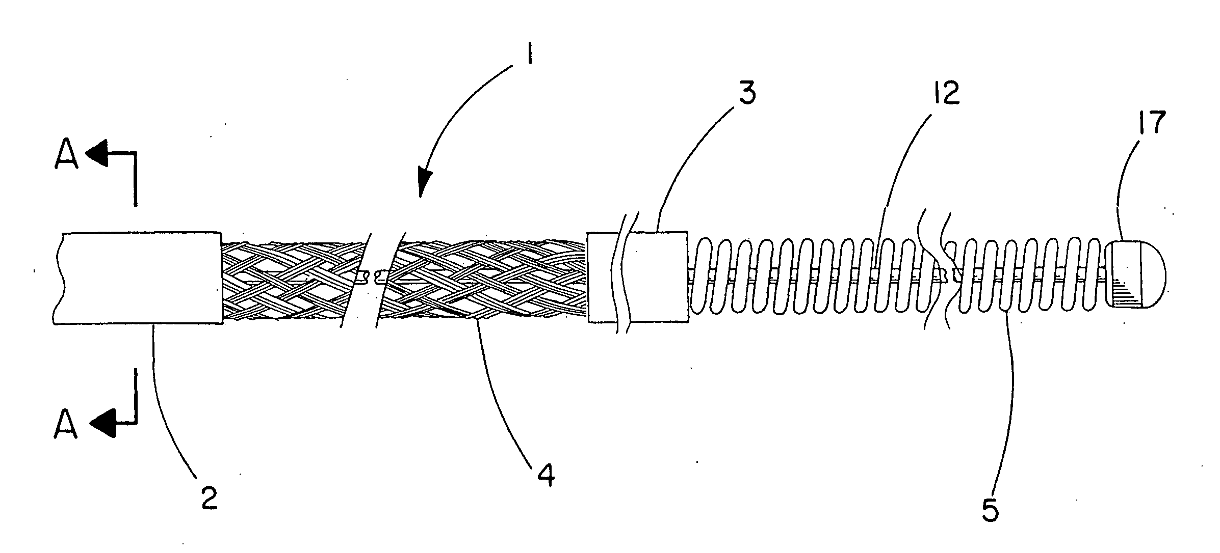
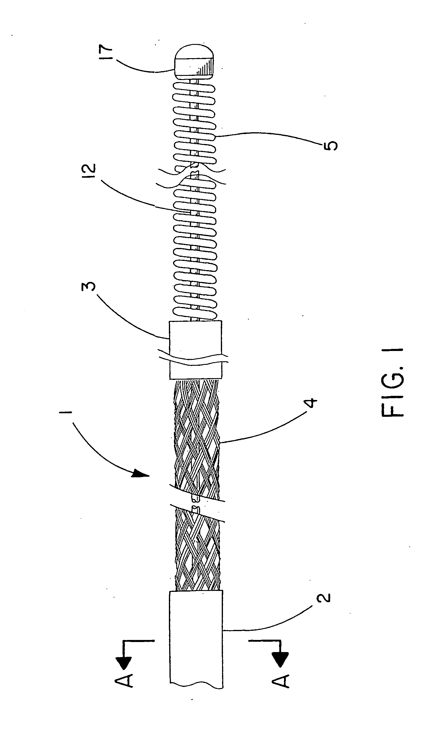
[0040]The cerebral vasculature device comprises:

[0041]Continuous braided structure comprising a plurality of wires, the braided structure having a proximal portion, a distal portion, a first expandable portion between the proximal portion and the distal portion, and a lumen extending from the proximal portion to the distal portion;

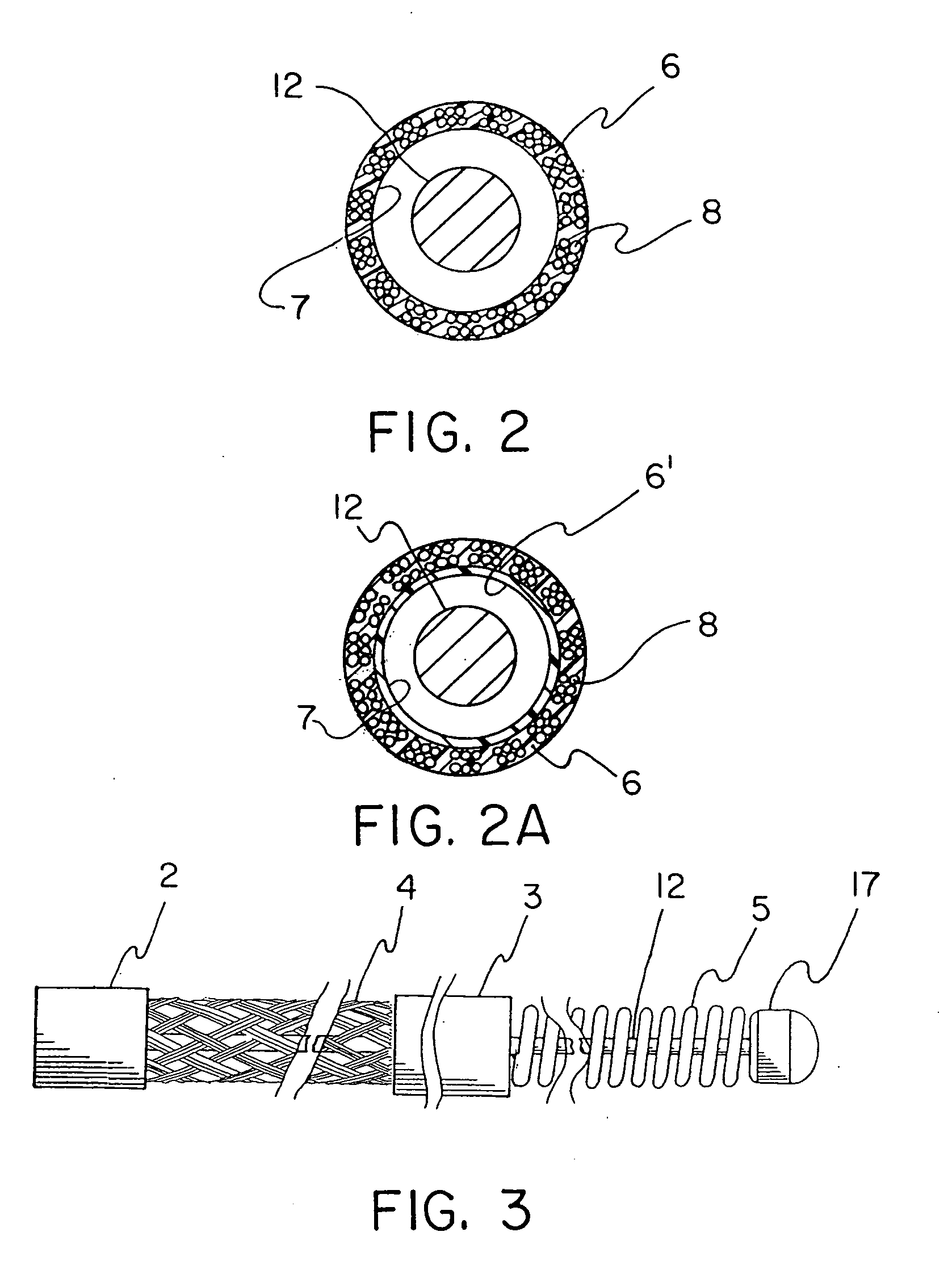
[0042]The proximal portion and the distal portion each having an outer diameter and an inner diameter and further including polymer imbedded at least partially into the braided structure;

[0043]Core wire having a proximal end and a distal end, the core wire located within the lumen and extending from the braided structure proximal portion to a point at or distal to the braided structure distal portion; and

[0044]Atraumatic component attached to the core wire distal end and having an outer diameter at least equal to the inner diameter of the braided structure distal portion.

[0045]The invention is best understood with reference to the several figures that demo...


PUM


Abstract

Novel cerebral vasculature devices are disclosed, including thrombectomy removal devices that include a continuous braided structure, a proximal portion, a distal portion, and a first expandable portion located between the proximal portion and the distal portion. The braided structure includes a plurality of wires. The proximal portion and the distal portion include polymer imbedded at least partially into the braided structure. The device is useful for removing thrombus from a patient's vasculature.

Description

BACKGROUND OF THE INVENTION[0001]1. Field of the Invention[0002]The present invention relates to devices useful for removing objects such as thrombus / or other foreign bodies from a patient's vasculature. More particularly, the invention relates to devices useful for removing thrombus from a patient's cerebral vasculature.[0003]2. Description of Related Art[0004]The use of a mechanical means to restore patency to obstructed vessels is well known. These devices fit into many categories ranging from hydraulic removal of thrombus, rotating cutting blades for calcified plaque, inflatable means for crushing or dragging thrombus, or a multiplicity of metal structures that either self-expand or can be expanded to dredge a vessel or remove a stone.[0005]Examples of these devices date back to the ‘Fogarty Catheter’ described by Fogarty in U.S. Pat. Nos. 3,367,101; 3,435,826; and 4,403,612 describing in detail improvements to a balloon catheter for embolectomy purposes. While suitable for many...

Claims


Application Information

Patent Timeline
Patent Type & Authority Applications(United States)
IPC IPC(8): A61M25/00
CPCA61B17/12022A61F2230/0078A61B17/12109A61B17/12113A61B17/1214A61B17/12172A61B17/221A61B2017/12127A61F2/013A61F2002/016A61F2002/018A61F2230/0065A61F2230/0069A61F2230/0071A61B17/12045D04C1/06D10B2101/20D10B2509/06A61B17/320725A61B2017/320716
Inventor TRAPP, BENJAMIN M.FRIEDMAN, NATHAN L.VONESH, MICHAEL J.
Owner WL GORE & ASSOC INC
Why Eureka
Try Eureka