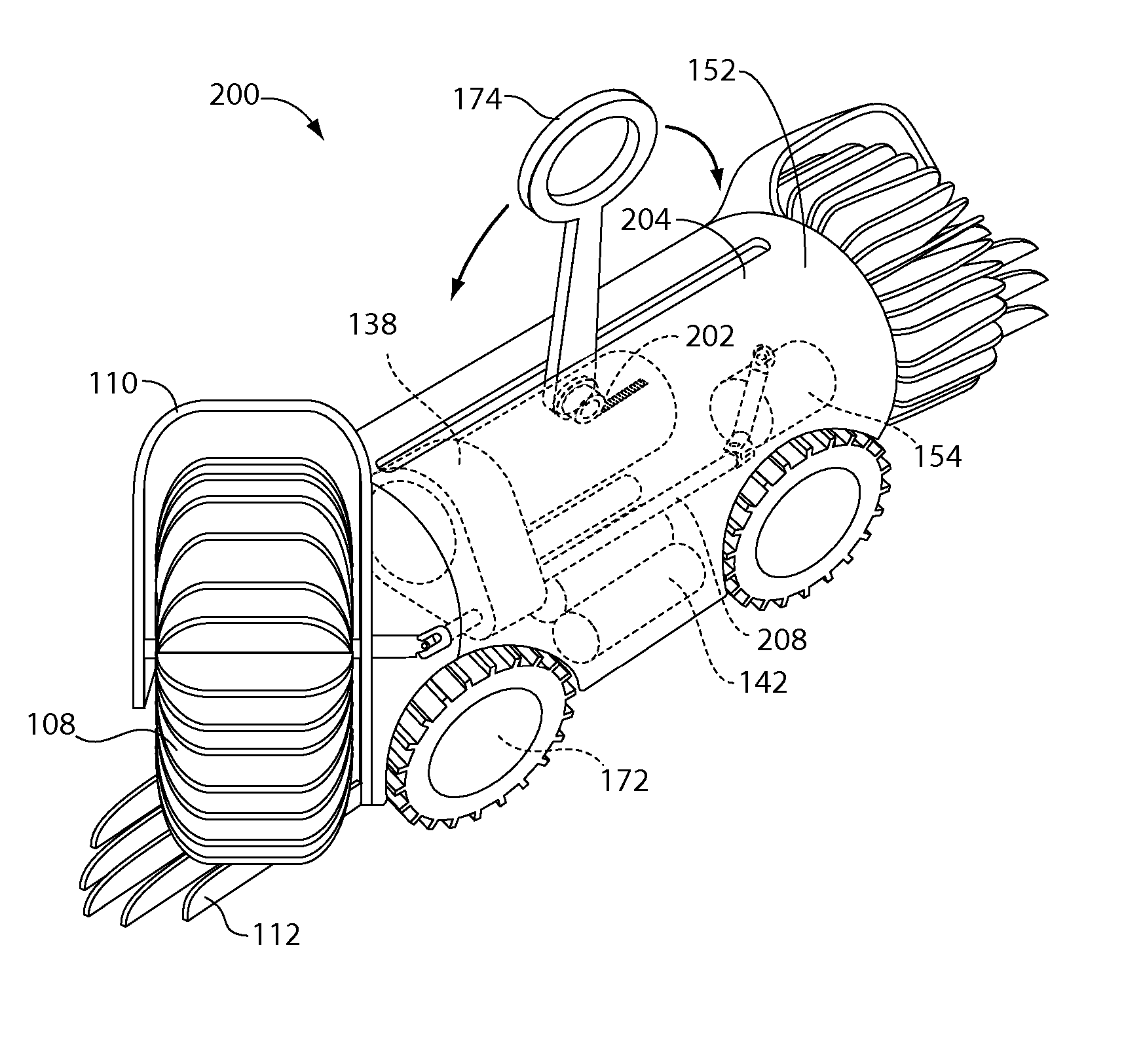
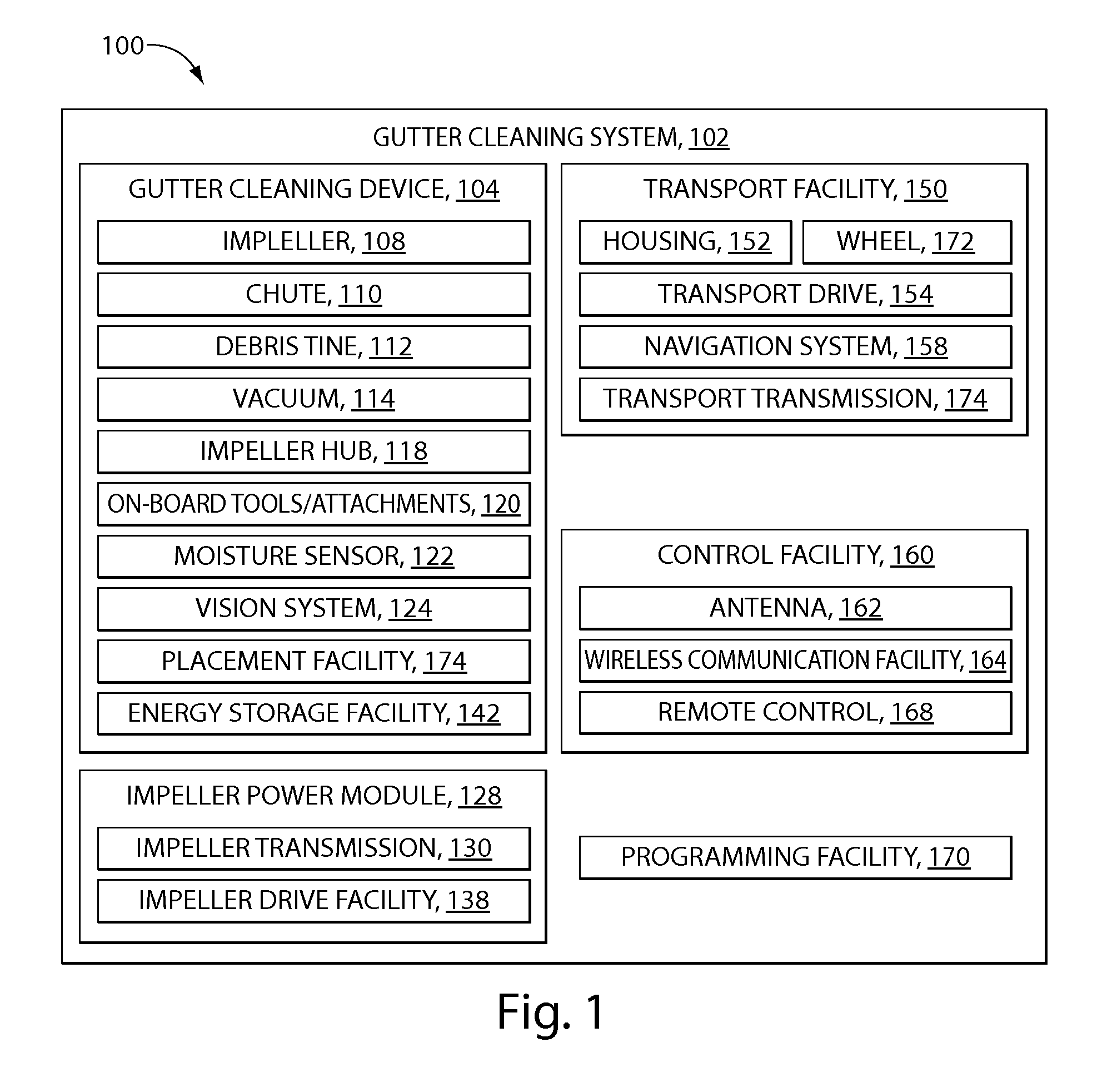
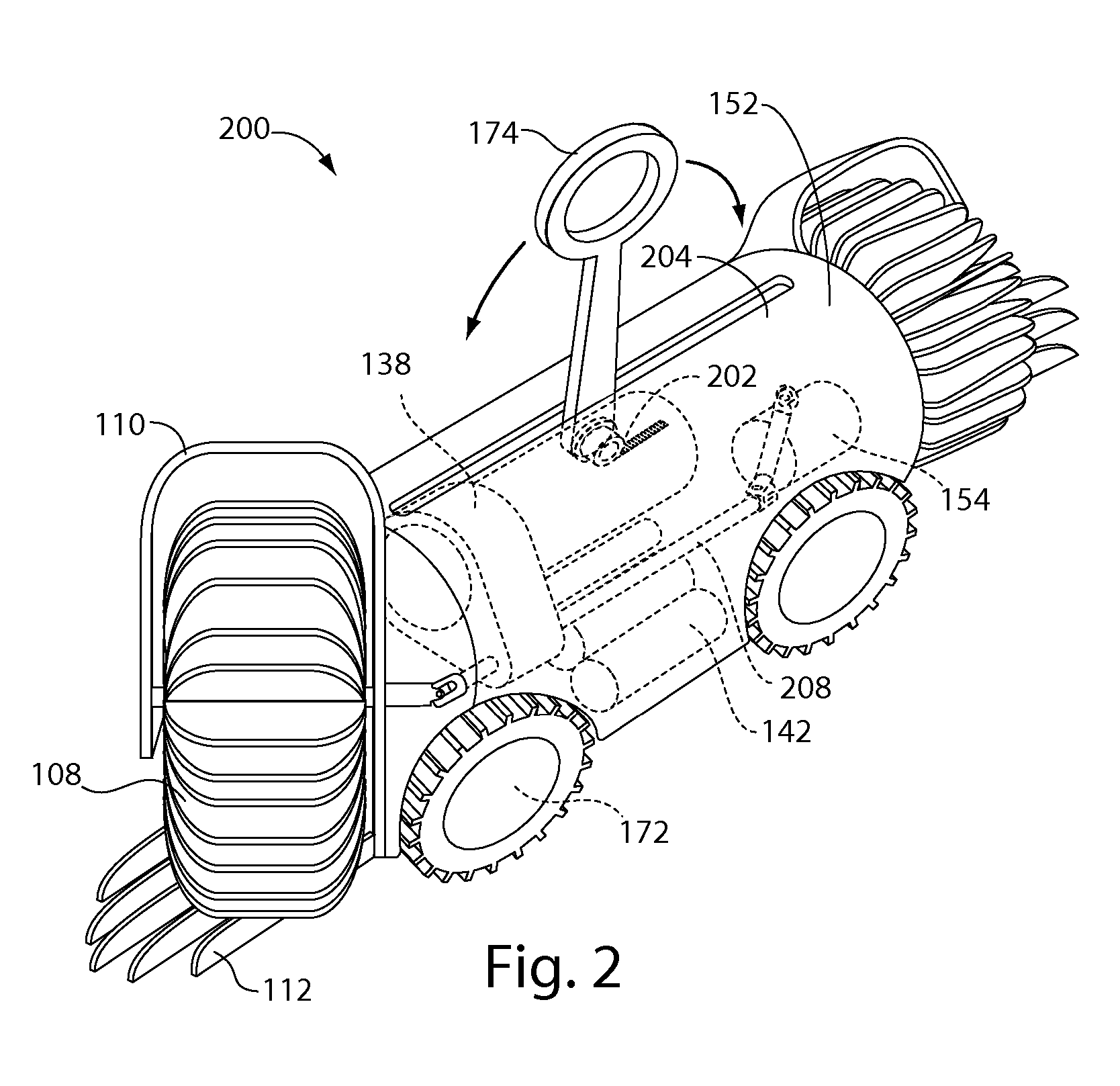
[0006] Provided herein may be methods and systems for gutter cleaning and a gutter-cleaning device thereof. In an aspect of the invention, a gutter-cleaning device includes a housing containing an impeller drive facility, the housing configured to fit into a gutter; an impeller, disposed at an end of the housing and driven by the impeller drive facility; and a transport facility for transporting the housing along the gutter. In the device, the impeller may be removably connected. In the device, the impeller drive facility may include a transmission. In the device, the impeller may be a rotating impeller. In the device, the impeller may be configured to remove debris from a gutter. In the device, the housing may include an energy storage facility. In the device, the device may further include a placement facility for facilitating placement of the gutter-cleaning device into a gutter. A placement pole, optionally telescoping, may attach to a placement facility to facilitate placing the gutter-cleaning device in the gutter. The placement facility may be spring-loaded to keep the placement facility vertical unless a lateral force is applied to the placement facility. In the device, the device may further include a control facility. The control facility may include an antenna. The antenna may be integrated with a placement facility. The control facility may be a remote control facility. The remote control facility may include a wireless communication facility. In the device, the transport facility may include a rotational transport facility. In the device, the device may further include an impeller chute for housing a portion of the impeller, wherein debris may be rotated against the chute by the impeller prior to ejection from the gutter. In the device, the device may further include debris tines disposed at one or both ends of the gutter-cleaning device to loosen and lift matted debris from the bottom and sides of the gutter into the impeller. The debris tines may be formed from at least one of metal, wood, plastic, and molded elastomer. The debris tines may be coated with a solid debris removal solvent. The impeller may be formed from at least one of a molded elastomer, neoprene, rubber, plastic, and an electrostatic cloth. The impeller may be at least one of a helical-bristled brush, a flexible paddle, a full stiff bristle brush, a spiral stiff bristle brush, a wire brush, a dethatching brush, an alternating paddle brush, a flexible bucket, a multiply-vaned impeller, and an alternating flexible blade. In the device, the transport facility may be at least one of a wheel, a snake drive, a worm drive, a crab or walking drive, a scoot-and-compress or accordion drive, and a string of beads drive. The wheel may be at least one of a tractor/tread wheel and tractor treads/tracks, finned hemispherical wheels, rubber wheels, vulcanized wheels, plastic wheels, molded elastomer wheels, and metal wheels. The wheel may be connected through an axle to a drive shaft. In the device, the device may further include a vision system disposed on the housing for facilitating navigation and programming of the device. The vision system may include a solid state camera, a camera lens, and a video signal electronics module. In the device, the device may further include a moisture sensor for detecting prohibitive levels of moisture in a gutter. In the device, the transport facility and the impeller drive facility may each control both transport and impellers. In the device, the device may further include at least one of an on-board tool or attachment, a downspout cleaning tool, an air hose attachment, a water hose attachment, a vacuum facility, and a weed whacker attachment. The vacuum facility may provide a vacuum through at least one of the impellers, the impeller vane attachment point, the housing, and a vacuum hose attachment. In the device, the impeller drive facility may be at least one of a reversing gear motor, an electric motor, a gasoline- or biofuel-powered internal combustion engine, and a solar-powered motor. In the device, the transport facility may be at least one of a reversing gear motor, an electric motor, a gasoline- or biofuel-powered internal combustion engine, and a solar-powered motor. In the device, the housing may be formed from at least one of metal, plastic, molded elastomer, weather-resistant materials, water-resistant materials, solvent-resistant materials, temperature-resistant materials, shock-resistant materials, and breakage-resistant materials. In the device, the device may further include a navigation system to facilitate autonomous control of the device. The navigation system may be integrated with at least one of a proximity sensor, a vision system, a programming facility, and a moisture sensor. In the device, the device may further include an energy storage facility connected to the transport and impeller drives for providing power. The energy storage facility may be at least one of a battery, a gasoline fuel or biofuel tank, and a solar panel. The battery may be at least one of rechargeable, disposable, lead-acid, gel, nickel cadmium, nickel metal hydride, lithium ion, zinc carbon, zinc chloride, alkaline, silver oxide, lithium ion disulphide, lithium thionyl chloride, mercury, zinc air, thermal, water activated, and nickel oxyhydroxide. In the device, the device may further include a programming facility to set programs for autonomous control. Programming may be done by at least one of wirelessly and a direct connection to a programming interface.
[0007] In an aspect of the invention, a gutter cleaning system includes a gutter-cleaning device, further including: a housing, the housing configured to fit into a gutter; and an impeller, disposed at an end of the housing and driven by an impeller drive facility; and a placement pole, optionally telescoping, operably connected to the gutter-cleaning device, further including: an impeller drive facility electrically connected to an impeller; optionally, a transport facility for transporting the housing along the gutter; and an energy storage facility electrically connected to the impeller drive facility and the transport facility for providing power. In the device, the impeller may be removably connected. In the device, the impeller drive facility may include a transmission. In the device, the impeller may be a rotating impeller. In the device, the impeller may be configured to remove debris from a gutter. In the device, the housing may include an energy storage facility. In the device, the device may further include a control facility. The control facility may include an antenna. The control facility may be a remote control facility. The remote control facility may include a wireless communication facility. In the device, the transport facility may include a rotational transport facility. In the device, the device may further include an impeller chute for housing a portion of the impeller, wherein debris may be rotated against the chute by the impeller prior to ejection from the gutter. In the device, the device may further include debris tines disposed at one or both ends of the gutter-cleaning device to loosen and lift matted debris from the bottom and sides of the gutter into the impeller. The debris tines may be formed from at least one of metal, wood, plastic, and molded elastomer. The debris tines may be coated with a solid debris removal solvent. The impeller may be formed from at least one of a molded elastomer, neoprene, rubber, plastic, and an electrostatic cloth. The impeller may be at least one of a helical-bristled brush, a flexible paddle, a full stiff bristle brush, a spiral stiff bristle brush, a wire brush, a dethatching brush, an alternating paddle brush, a flexible bucket, a multiply-vaned impeller, and an alternating flexible blade. In the device, the transport facility and the impeller drive facility may each control both transport and impellers. In the device, the device may further include at least one of an on-board tool or attachment, a downspout cleaning tool, an air hose attachment, a water hose attachment, a vacuum facility, and a weed whacker attachment. The vacuum facility may provide a vacuum through at least one of the impellers, the impeller vane attachment point, the housing, and a vacuum hose attachment. In the device, the impeller drive facility may be at least one of a reversing gear motor, an electric motor, a gasoline- or biofuel-powered internal combustion engine, and a solar-powered motor. In the device, the transport facility may be at least one of a reversing gear motor, an electric motor, a gasoline- or biofuel-powered internal combustion engine, and a solar-powered motor. In the device, the housing may be formed from at least one of metal, plastic, molded elastomer, weather-resistant materials, water-resistant materials, solvent-resistant materials, temperature-resistant materials, shock-resistant materials, and breakage-resistant materials. In the device, the device may further include a navigation system to facilitate autonomous control of the device. The navigation system may be integrated with at least one of a proximity sensor, a vision system, a programming facility, and a moisture sensor. In the device, the device may further include an energy storage facility connected to the transport and impeller drives for providing power. The energy storage facility may be at least one of a battery, a gasoline fuel or biofuel tank, and a solar panel. The battery may be at least one of rechargeable, disposable, lead-acid, gel, nickel cadmium, nickel metal hydride, lithium ion, zinc carbon, zinc chloride, alkaline, silver oxide, lithium ion disulphide, lithium thionyl chloride, mercury, zinc air, thermal, water activated, and nickel oxyhydroxide. In the device, the device may further include a programming facility to set programs for autonomous control. Programming may be done by at least one of wirelessly and a direct connection to a programming interface. In the device, the placement pole may be removably associated with the gutter-cleaning device.
[0008] In an aspect of the invention, a method of a gutter-cleaning device may include providing a housing containing an impeller drive facility, the housing configured to fit into a gutter; disposing an impeller at an end of the housing and driving the impeller with the impeller drive facility; and providing a transport facility for transporting the housing alo

