Measurement marker

a measurement marker and tape measure technology, applied in the field of carpentry tools, can solve the problems of multiple opportunities for disparities to be introduced, errors can be introduced, and operators may simply misread the indicia marking on the tape, so as to facilitate the measurement of a distance and achieve accurate transfer of that measured distan

Inactive Publication Date: 2008-05-01
LIPPS DANIEL
View PDF15 Cites 31 Cited by
  • Summary
  • Abstract
  • Description
  • Claims
  • Application Information

AI Technical Summary

Benefits of technology

[0019]In view of the foregoing disadvantages inherent in the known tape measure devices now present in the prior art, the present invention provides an attachment for a common tape measure that facilitates the measurement of a distance between two reference points, and the accurate transfer of that measured distance to a work piece, and a method of using same.

Problems solved by technology

A problem with this prior method of taking and transferring measurements, using common tape measures, is that there are several opportunities for disparities to be introduced between the actual length between points on the reference structure and the marked length on the work piece.
For example, in the prior method errors can be introduced during the reading of the measurement between the first and second points on the reference structure.
That is, the operator may simply misread the indicia marking on the tape.
Such bending can introduce error into the measurement, and such spacing of the edge of the tape away from the measured point can introduce parallax error into the measurement.
Such approximation or calculated interpolation can introduce error into the measurement.
Also, because the operator must make a note of, and subsequently recall, the measured length (between points on the reference structure) there are two additional opportunities for error to be introduced into the measurement.
Such errors could be introduced, for example, if the measurement were incorrectly noted or incorrectly recalled.
A problem of this prior device is that it is bulky, has several parts, and involves fastening to the tape measure housing, and the bottom portion of the device inherently prohibits the (concavo-convex) tape from lying directly against a work piece.
Although the anchor hook on this prior device may assist in securing the free end to certain types of work pieces, it does not aid in identifying the location along the tape at which a measured work piece is to be marked.
None of these prior devices facilitates making a mark on a work piece at an intermediate location along the measuring tape; and, because of their downward depending appendages, none of these prior devices allows the measuring tape to lie directly against the work piece in the area directly beneath the appendage.
Furthermore, none of these prior attachment devices is designed to facilitate the taking of a measurement between two spaced apart points on a reference structure.

Method used


Image

  • Measurement marker
  • Measurement marker
  • Measurement marker

Examples


Embodiment Construction

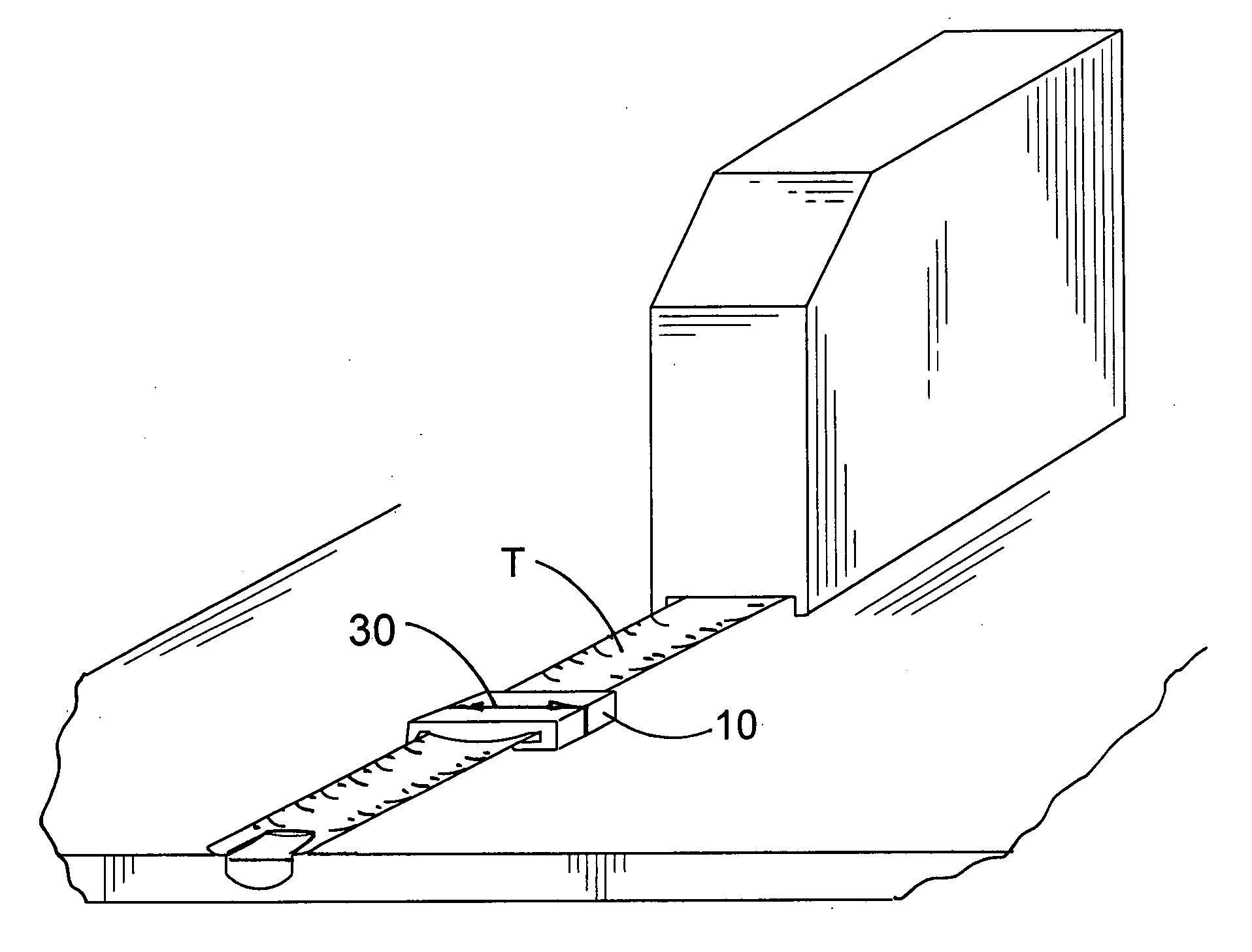
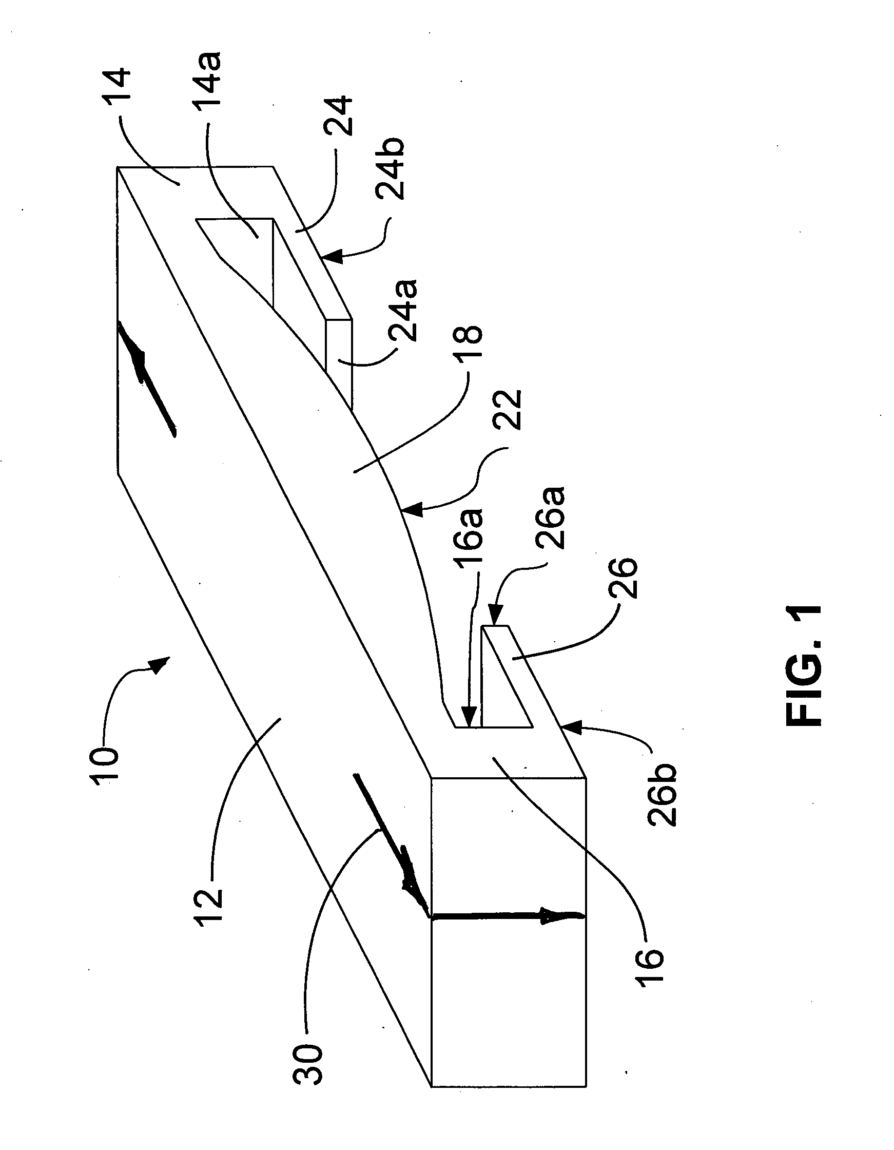
[0068]Referring to FIGS. 1 through 4, in which are shown a preferred embodiment of a tape measure marking guide 10 in accordance with the present invention: Marking guide 10 is designed to be operationally used in conjunction with, and attachable to, a common measuring tape blade (T), which may be normally retractably stored in a coiled condition within a tape measure casing, and which may be normally extracted in a substantially straight line from the tape measuring case, and which nominally has a concavo-convex transverse cross-section, and which has graduated indicia markings along its length to function as a measuring scale.

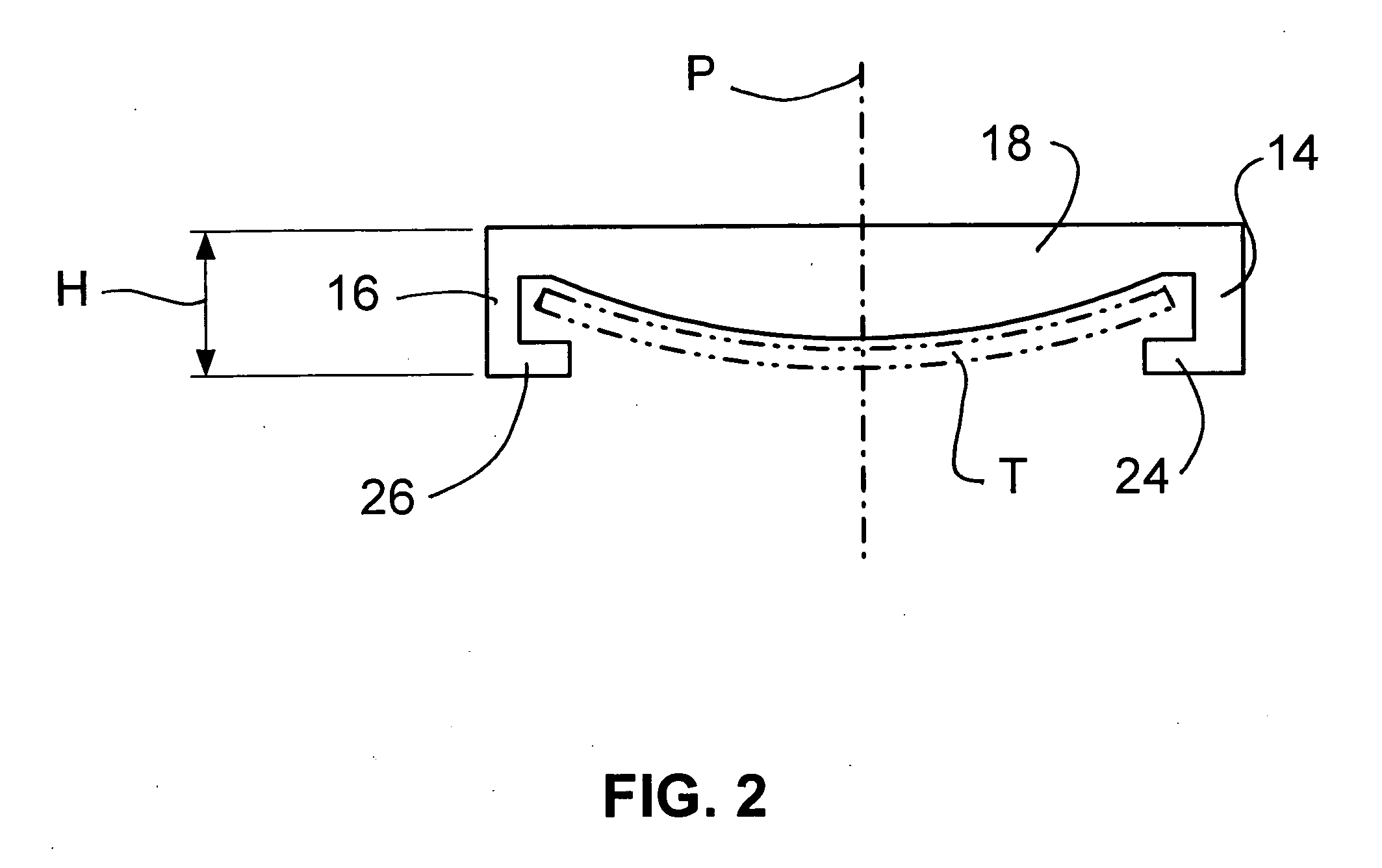
[0069]Marking guide 10 has opposing first 14 and second 16 side walls depending downwardly from a central body portion 18. Central body portion 18 has a top surface 12 and an underside surface 22.

[0070]First 24 and second 26 flanges extend from, and are directed inwardly toward each other from, first 14 and second 16 side walls, respectively. The central body...


PUM


Abstract

A tape measure marker device is attachable to a common tape measure blade. The marker device has a central body portion with a pair of downwardly depending legs, each with an inwardly facing flange that helps hold the marker device to the tape measure blade. The ends of the facing flanges are spaced apart and together with the underside of the two legs and the central body portion form an open cavity that is configured to receive a common tape measure blade. The convex underside of the central body portion is adapted to nest with the top face of the tape measure blade. In operation, the marker device is manually slid along the tape measure blade until a registration mark, which may be printed, embossed or engraved on the surface of the device, aligns with a point that is to be measured. The coplanar underside of the flanges on the device allows the marker device and the tape measure blade to lie directly against a device that is to be measured. In a preferred embodiment the marker device is constructed of a resilient transparent or translucent resilient so that the graduated indicia markings on the measuring tape can be seen through the device, and so that the legs of the device can temporarily be manually spread apart wide enough for insertion of the tape measure blade.

Description

BACKGROUND OF THE INVENTION[0001]1. Field of the Invention[0002]The present invention relates generally to carpentry tools. More particularly, the present invention relates to an improved tape measure attachment apparatus that can be used as a measurement marking gauge.[0003]2. Description of the Prior Art[0004]Standard tape measures include a length of tape wound on a spool with a spring return mechanism so that, after the tape is taken out of a housing, the spring return mechanism can automatically retract the tape into the housing. Many common tape measures are provided with a locking mechanism, typically a sliding button, which locks the tape for the purpose of reading the length of the deployed tape. Graduated indicia markings along the length of the tape function as a measuring scale. In most common tape measures, in order to provide strength to the unwound length of tape, and to keep the unwound length of tape in a straight line, and to aid in proper rewinding of the tape ins...

Claims


Application Information

Patent Timeline
Patent Type & Authority Applications(United States)
IPC IPC(8): G01B3/10
CPCG01B2003/1089G01B3/1084G01B3/1089
Inventor LIPPS, DANIEL
Owner LIPPS DANIEL
Why Eureka
Try Eureka