Optical ranging device for automobile

A technology for optical ranging and vehicle use, which is applied to measuring devices, distance measurement, line-of-sight measurement, etc.

Active Publication Date: 2016-08-31
徐斌
View PDF5 Cites 0 Cited by
  • Summary
  • Abstract
  • Description
  • Claims
  • Application Information

AI Technical Summary

Problems solved by technology

[0008] However, it is not always possible to be lucky enough to see the horizon. When there are uphills, buildings or mountains in the distance, the position of the horizon cannot be determined, that is, the above-mentioned observation horizon cannot be determined, and thus the distance cannot be measured.

Method used


Image

  • Optical ranging device for automobile
  • Optical ranging device for automobile
  • Optical ranging device for automobile

Examples


Embodiment 1

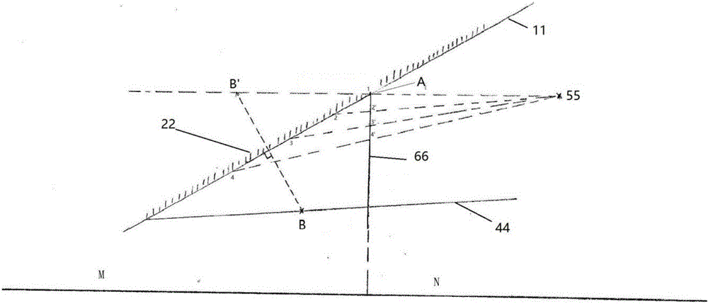
[0044] The overall overview of the technical solution is: windshield scale ruler + reference point of mirrored eye level, see diagram figure 2 . The eye-level reference point B in the figure is a point printed or installed at a specific position on the instrument panel using materials that are easy to produce obvious mirror images (high-recognition colors, fluorescent materials, luminous materials or electronic light-emitting devices). The mirror image B'and the eye level reference point A on the windshield determine the observation eye level. When the two points in the human eye line of sight coincide, the distance measurement can be performed. The eye level reference point A is located on the windshield, for example, it can be located directly in front of the driver, and its height is approximately the same as the height of the human eye 55. The eye level reference point B can be located on the car dashboard, and the driver can adjust the position of the eye level reference ...

Embodiment 2

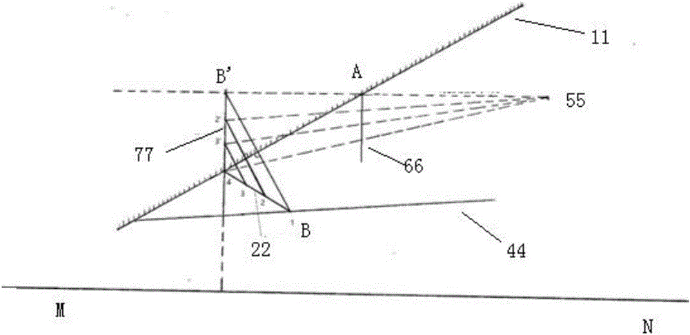
[0046] The overall overview of the technical solution is: mirror scale scale + windshield reference point, see the schematic diagram image 3 . image 3 Among them, the scale ruler seen by the human eye is also composed of mirror images. The method is to make a series of scales on dark materials using materials that are easy to produce mirror images (high-recognition colors, fluorescent materials, luminous materials or electronic light-emitting devices) (1, 2, 3, 4...), which becomes the physical scale scale, which is placed under the windshield, its first end is used as the eye-level reference point B, and its second end extends toward the windshield, which can be connected to the windshield Wind glass intersect or disjoint. The physical scale scale is imaged as a mirror scale scale in the windshield. The eye-level reference point A is still pre-made on the windshield. Adjust the position of the physical scale ruler so that the uppermost scale (1') of the mirror image and poin...

Embodiment 3

[0048] The overall overview of the technical solution is: mirror scale scale + eye level reference rod, see diagram Figure 4 .

[0049] In this solution, the eye-level reference point A on the windshield in Example 2 is also canceled, so that it is not necessary to make a reference point on the windshield in advance. Instead, an eye-level reference rod 3 is used. The ends are used as the eye-level reference point A and the eye-level reference point B respectively. Such as Figure 4 As shown, by pre-calibrating, adjust the placement position and angle of the eye level reference rod 3 so that the eye level reference point A and eye level reference point B at both ends are mirror points in the baffle glass. The reference point A'and the eye level reference point B'are on the observation eye level. Fix the position of the eye level reference rod and use it for distance measurement. The scale ruler still uses the mirror image of the physical scale ruler in the windshield. Figure 4...


PUM


Abstract

The invention discloses an optical ranging device for an automobile. According to the device, a visual borizon reference point A is set on a front windshield of the automobile, a visual borizon reference point B is set below the windshield, the observing visual borizon is determined by judging whether a mirror point B' of the visual borizon reference point B in the windshield coincides with the visual borizon reference point A or not, and the distance between an object in the distant place and a driver is directly observed through a mirror image of a scaleplate printed or stuck on the windshield or an objective scaleplate located below the windshield in the windshield according to the similar triangle principle. The device changes visual range estimation into actual ranging, is simple, easy to operate and low in cost and can be not only independently used by serving as an automobile accessory, but also prefabricated in a naked automobile just leaving a factory.

Description

Technical field [0001] The invention belongs to the field of vehicle equipment, and specifically relates to an optical distance measuring device for vehicles. Background technique [0002] Automobile drivers often need to judge the distance between distant targets and themselves, but they are often only estimated visually, which is difficult to estimate quantitatively. [0003] A simple quantitative estimation method is to use geometric calculation methods, such as figure 1 As shown, a scale ruler is placed vertically in front of the driver’s eyes, where H is the height of the human eye to the ground, h is the height of the line of sight on the scale when observing the grounding point of the distanced object, D is the measured distance, d It is the horizontal distance between the human eye and the scale ruler. Due to the principle of similar triangles: [0004] D / d=H / h [0005] Then D=Hd / h Formula 1 [0006] Among them, H and d are calibrated in advance and are known quantities, and ...

Claims


Application Information

Patent Timeline
Patent Type & Authority Applications(China)
IPC IPC(8): G01C3/24
CPCG01C3/24
Inventor 徐斌
Owner 徐斌
Why Eureka
Try Eureka