Sensor utilizing ultrasonic transducer and method for reducing ringing time thereof

A technology of ringing time and transducer, which is applied in the re-radiation of sound waves, the use of sound waves/ultrasonic waves/infrasonic waves for material analysis, and the use of re-radiation, etc., can solve problems such as the inability to measure distances, shorten the minimum distance, and improve performance, the effect of reducing the ringing time

Inactive Publication Date: 2021-08-10
ABOV SEMICON
View PDF7 Cites 0 Cited by
  • Summary
  • Abstract
  • Description
  • Claims
  • Application Information

AI Technical Summary

Problems solved by technology

At this time, the signal of the reflected wave ES of the object is weak, but on the contrary, the after-oscillation ultrasonic signal RS has a larger amplitude than the reference amplitude L of the reflected wave ES in a relatively long time period Zd, so in the time period Zd, even if Received reflected wave ES can not measure the accurate distance
That is, although the driving time of applying the electric driving signal DS is t0, due to aftershock, the piezoelectric film needs to become stable before time t1 until the minimum distance can be measured

Method used


Image

  • Sensor utilizing ultrasonic transducer and method for reducing ringing time thereof
  • Sensor utilizing ultrasonic transducer and method for reducing ringing time thereof
  • Sensor utilizing ultrasonic transducer and method for reducing ringing time thereof

Examples


Embodiment Construction

[0051] In addition to the above objects, other objects and features of the present invention will become apparent by describing embodiments with reference to the accompanying drawings.

[0052] Preferred embodiments of the present invention will be described in detail with reference to the accompanying drawings. In describing the present invention, when it is judged that a detailed description of a related known structure or function may obscure the gist of the present invention, the detailed description thereof will be omitted.

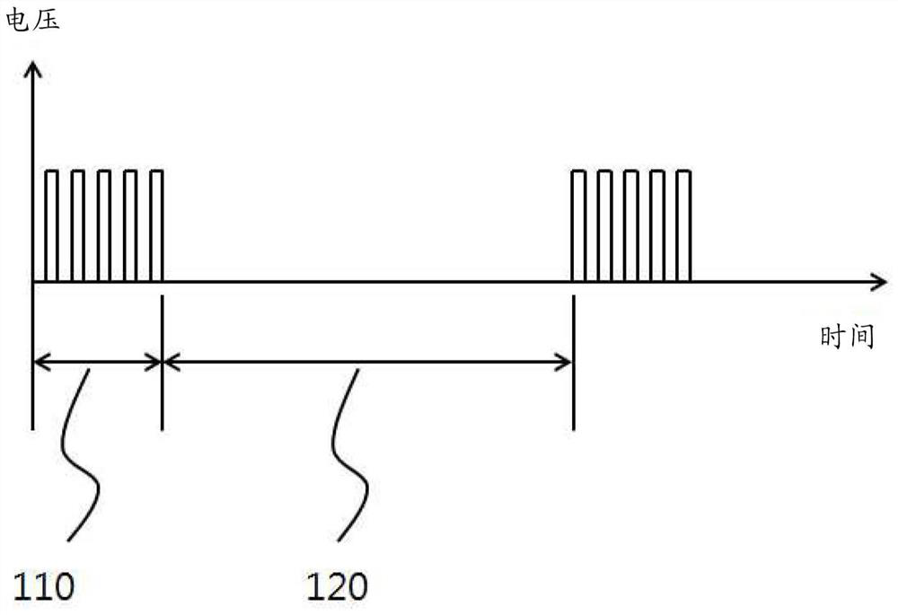
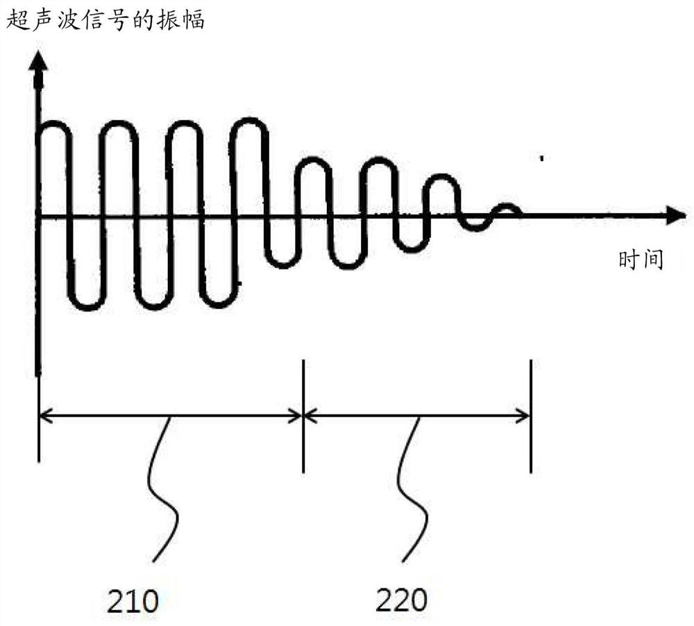
[0053] The ultrasonic transducers involved in the description of the present invention mainly use piezoelectric films (Piezoelectric Film). When an ultrasonic transducer generates an ultrasonic signal, the piezoelectric effect in which a piezoelectric film is vibrated by applying an electrical signal with repeated pulses or an AC waveform is utilized. At this time, the frequency of the pulse wave or the AC waveform is preferably set to a natural fre...


PUM


Abstract

A sensor utilizing an ultrasonic transducer is disclosed. The sensor includes a sending circuit module and a receiving circuit module, the sending circuit module applies a first electric drive signal including a plurality of pulses to the ultrasonic transducer, and the receiving circuit module detects the reflected wave received by the ultrasonic transducer and generates a receiving electrical signal , wherein, after applying the first electric drive signal, the transmitting circuit module applies to the ultrasonic transducer a second electric drive signal comprising a plurality of anti-phase pulses having an anti-phase relationship with the first electric drive signal, and the multiple The anti-phase pulses are controlled to apply sequentially decreasing energy from pulse to pulse to the ultrasound transducer.

Description

technical field [0001] The present invention relates to a distance sensor using an ultrasonic transducer and a method for reducing the ringing time of the distance sensor, in particular to a circuit and a method for reducing the ringing time by controlling the driving pulse signal of the ultrasonic transducer. Background technique [0002] Sensors that use ultrasonic waves to measure distances sense signals received by reflections from objects after sending out ultrasonic waves. At this time, the time interval between the transmitted ultrasonic signal and the received ultrasonic signal is measured, and the distance from the point where the ultrasonic wave is transmitted to the object is measured by distance calculation considering the speed of sound wave transmission. [0003] At this time, in many cases, the device that transmits the ultrasonic wave vibrates the Piezoelectric Film (Piezoelectric Film) transducer, etc. through an electric drive signal of a specific frequency...

Claims


Application Information

Patent Timeline
Patent Type & Authority Patents(China)
IPC IPC(8): G01S15/08
CPCG01S15/08G01N29/348G01N29/40G01N29/4418G01S7/527G01S7/529
Inventor 李永真闵庆波金昌民
Owner ABOV SEMICON
Why Eureka
Try Eureka